


INPUT DCA/GROUP function
296 PM5D/PM5D-RH V2 / DSP5D Owner’s Manual Reference section
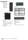
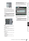
B GANG
C Delay time knob
D DELAY ON/OFF
These are the same as in the OUTPUT DELAY func-
tion (➥ p.258).
E Channel
This area shows the number and name of the input
channel you are editing. Two paired channels (or a ST
IN channel) are indicated by a heart symbol displayed
between them. You can click this symbol to enable/dis-
able pairing.
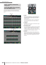
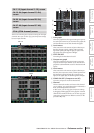
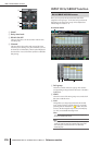
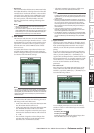
INPUT DCA/GROUP function
Here you can specify the input channels that will be
assigned to DCA groups 1–8. The level of input channels
belonging to the same DCA group can be adjusted as a
whole using DCA faders 1–8.
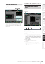
A DCA group
This is the number of the DCA group. The number
corresponding to the grid where the cursor is located is
highlighted.
B Name
This is the name of the DCA group. You can also click
this area to edit the name.
C Grid
This grid lets you assign input channels (horizontal
rows) to DCA groups (vertical columns). Currently-
patched grids are indicated by a symbol. Move the
cursor to the desired grid and press the [ENTER] key
(or click) to set/disable the assignment.
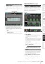
Hint
You can also assign a single input channel to multiple DCA
groups for multiple DCA control.
Hint
DCA groups 1–6 are for input channels only, but DCA groups
7/8 can be used with both input channels and output chan-
nels. Both types of channel can exist in an identically-
numbered group.
2
4
3
5
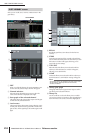
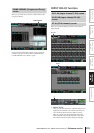
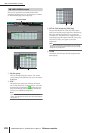
DCA GROUP ASSIGN screen
DCA GROUP ASSIGN
21 3