


PM5D/PM5D-RH V2 / DSP5D Owner’s Manual Reference section 293
Information shown
in the display
Function
menu
Global
functions
Output
functions
Input
functions
Appendices
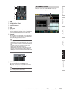
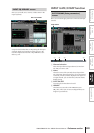
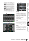
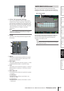
These screens list the gate/compressor settings for the input
channels. Here you can also copy gate/compressor settings
between input channels.
A Gate graph
This mini-graph shows the approximate gate response
for each input channel. If you click the mini-graph, the
GATE PARAM screen for that channel will appear.
B Level meters
These meters show the amount of gain reduction pro-
duced by the gate (at left), and the peak level of the
signal after passing through the gate (at right). If the
signal clips, the OVER segment will light.
C GATE ON/OFF
Turns the gate for that channel on/off.
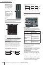
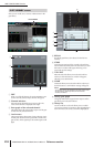
D Compressor graph
This mini-graph shows the approximate compressor
response for each input channel. If you click the mini-
graph, the COMP PARAM screen for that channel will
appear.
E Level meters
These meters show the amount of gain reduction pro-
duced by the compressor (at left), and the peak level of
the signal after passing through the compressor (at
right). If the signal clips, the OVER segment will light.
F COMP ON/OFF (Compressor on/off)
Turns the compressor on/off for that channel.
G Channel
This area shows the number and name of the channel
you are editing. Two paired channels are indicated by a
heart symbol displayed between them.
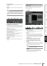
In this screen, you can copy gate/compressor settings
by dragging and dropping the mini-graph of a desired
channel onto another channel. You can also copy gate/
compressor settings between different screens (for the
procedure ➥ p.255).
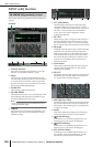
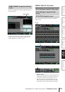
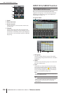
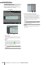
CH 1-12 (Input channel 1–12) screen
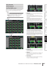
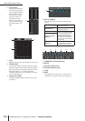
CH 13-24 (Input channel 13–24)
screen
CH 25-36 (Input channel 25–36)
screen
CH 37-48 (Input channel 37–48)
screen
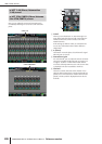
ST IN (ST IN channel) screen
CH 1-12
ST IN
3
6
5
7
2 1 4