


PM5D/PM5D-RH V2 / DSP5D Owner’s Manual Reference section 307
Information shown
in the display
Function
menu
Global
functions
Output
functions
Input
functions
Appendices
ALL PRE [ALL MIX ]
Specify pre-fader as the send position for signals sent
from the specified input channel to all MIX buses.
ALL POST [ALL MIX ]
Specify post-fader as the send position for signals sent
from the specified input channel to all MIX buses.
ALL PRE [ALL CH ]
Specify pre-fader as the send position for signals sent
from all input channels to the specified MIX bus.
ALL POST [ALL CH ]
Specify post-fader as the send position for signals sent
from all input channels to the specified MIX bus.
ALL PRE [ALL CH x ALL MIX]
Specify pre-fader as the send position for signals sent
from all input channels to all MIX buses.
ALL POST [ALL CH x ALL MIX]
Specify post-fader as the send position for signals sent
from all input channels to all MIX buses.
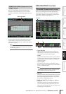
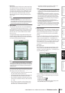
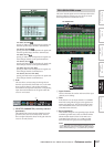
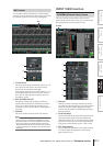
C Grid
This area shows various settings for the signals sent
from the input channels (horizontal rows) to the MIX
buses (vertical columns). The red lines extending
toward the left and upward indicate the corresponding
input channel and MIX bus for the grid at which the
cursor is now located.
D SELECTED PARAMETER (currently selected
parameter)
This indicates the input channel and MIX bus for the
grid where the cursor is currently located. The four
boxes at right indicate the values for the grid where the
cursor is currently located.
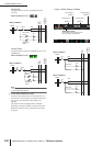
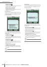
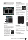
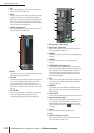
This screen lists the signals sent from the input channels to
the buses and direct outputs. You can also set or cancel
these assignments from within this screen.
A Input channel
This area indicates the number and name of the input
channel you are editing.
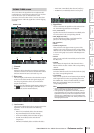
B PAN
If this button is on, the input channel’s TO STEREO
PAN knob setting will also apply to the signal sent to
FIXED-type MIX buses. This is linked with the FOL-
LOW PAN FIXED button of the CH to MIX screen
(PAN/ROUTING function).
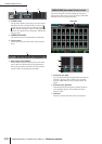
C Bus assignments
These buttons assign the corresponding input channel
to FIXED-type MIX buses. These are linked with the
SEND ON/OFF buttons of the CH to MIX screen
(PAN/ROUTING function). For VARI-type MIX
buses, the buttons are grayed-out and inoperable.
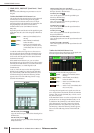
Note
If a surround mode other than STEREO is selected, the but-
tons for MIX buses used as surround buses will be named by
their surround channel (e.g., L, C, R) rather than by number.
4
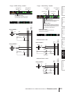
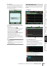
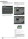
FIX ASSIGN VIEW screen
FIX ASSIGN VIEW
2
4
5
6
3
1