


PM5D/PM5D-RH V2 / DSP5D Owner’s Manual Reference section 227
Information shown
in the display
Function
menu
Global
functions
Output
functions
Input
functions
Appendices
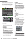
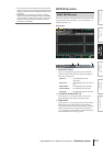
• DCA FADER MODE
Switching the mode of the top panel FADER MODE
section
• ENCODER MODE
Switching the mode of the top panel ENCODER
MODE section
• PANEL/LCD BRIGHTNESS
BRIGHTNESS settings in the PREFERENCE 2 screen
(UTILITY function)
• INPUT METER POINT/OUTPUT METER POINT/
PEAK HOLD
Input channel / output channel metering point selec-
tion, and peak hold on/off
• DCA LEVEL/MUTE
DCA group 1–8 level, name, [CUE] key on/off opera-
tions, and [MUTE] key on/off operations
Hint
DCA and MUTE parameter values will be linked the instant
Link is turned on. Other parameters will be linked for the first
time only when that parameter is operated after Link is turned
on.
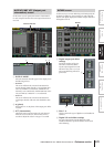
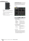
• MUTE MASTER
Mute group 1–8 on/off
Hint
• For details on the actual procedure of cascade-connecting
multiple PM5D/DSP5D units, refer to p.153.
• In the case of a system that is cascade-connected to the
DSP5D, the system will always operate as though the CAS-
CADE LINK area’s LINK button is on; this setting cannot be
changed. Other operations may also be linked.
• To enable cascade link, you must turn on linking for the cor-
responding parameters on the other cascade-connected
PM5D units as well.
• You can also turn linking off for the master PM5D. For
example if you’ve cascade-connected multiple PM5D units,
you can (for example) make settings so that DCA 1 is linked
only between the master and the second unit, DCA 2 is
linked for all PM5D units, and DCA 3 is linked only between
the second unit and third unit.
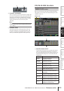
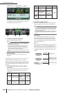
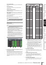
C CASCADE IN SOURCE (Cascade IN source I/
O assignment view)
Here you can view and select the signals that are sent to
the PM5D/DSP5D’s internal buses from the cascade-
connected external device. The type of signals received
will depend on the selection in the CASCADE FROM
field of the MIXER SETUP screen (SYS/W.CLOCK
function.)
D CASCADE IN ON/OFF
For each of the PM5D/DSP5D’s internal buses, you can
specify whether signals from the cascade master will be
input.
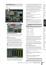
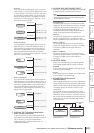
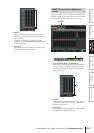
E PARAM LINK (parameter link)
For each pair of adjacent odd-numbered/even-num-
bered channels, this specifies whether the PM5D/
DSP5D’s channel parameters will be linked to output
the identical signal.
F CASCADE OUT ON/OFF
For each of the PM5D/DSP5D’s internal buses, you can
specify whether signals will be output to the cascade
slave.
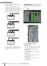
43 5 6
External device selected in the
CASCADE FROM field
Destina-
tion bus
PM5D/
DSP5D
*1
DM2000/
02R96
*1
MIXER
[30BUS]
MIXER
[16BUS]
*2
MIX 1 BUS 1
*3
SLOT4- 1 MIX 1
MIX 2 BUS 2 SLOT4-2 MIX 2
MIX 3 BUS 3 SLOT4-3 MIX 3
MIX 4 BUS 4 SLOT4-4 MIX 4
MIX 5 BUS 5 SLOT4-5 MIX 5
MIX 6 BUS 6 SLOT4-6 MIX 6
MIX 7 BUS 7 SLOT4-7 MIX 7
MIX 8 BUS 8 SLOT4-8 MIX 8
MIX 9 AUX 1 SLOT4-9 MIX 9
MIX10 AUX 2 SLOT4-10 MIX10
MIX11 AUX 3 SLOT4-11 MIX11
MIX12 AUX 4 SLOT4-12 MIX12
MIX13 AUX 5 SLOT4- 1 MIX13
MIX14 AUX 6 SLOT4- 2 MIX14
MIX15 AUX 7 SLOT4- 3 MIX15
MIX16 AUX 8 SLOT4- 4 MIX16
MIX17 AUX 9 SLOT4- 5 MIX17
MIX18 AUX10 SLOT4- 6 MIX18
MIX19 AUX11 SLOT4- 7 MIX19
MIX20 AUX12 SLOT4- 8 MIX20
MIX21 — SLOT4- 9 MIX21
MIX22 — SLOT4-10 MIX22
MIX23 — SLOT4-11 MIX23
MIX24 — SLOT4-12 MIX24
ST AL ST L SLOT4-13 ST AL
ST AR ST R SLOT4-14 ST AR
ST BL — SLOT4- 9 ST BL
ST BR — SLOT4-10 ST BR
CUE L CUE L SLOT4-15 CUE L
CUE R CUE R SLOT4-16 CUE R
*1. The signal assigned to each bus is fixed; it cannot be
changed.
*2. You can enable/disable the assignment for each bus.
However, you cannot send the signal of the same slot
or same input channel to multiple buses. If a signal
already assigned to a bus is selected for a different bus,
the previous assignment will be cancelled.
*3. Assigned from the top in ascending numerical order of
slot number / channel number, according to the settings
of the CASCADE IN PORT SELECT area of the
MIXER SETUP screen (SYS/W.CLOCK function). (this
cannot be changed.)