


PM5D/PM5D-RH V2 / DSP5D Owner’s Manual Reference section 233
Information shown
in the display
Function
menu
Global
functions
Output
functions
Input
functions
Appendices
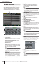
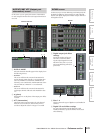
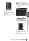
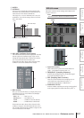
D Meters
These peak level meters indicate the output level of
each channel. The current master level value is shown
in the box below.
If clipping occurs at any point POST EQ, POST
COMP, POST ON, POST FADER, or INSERT IN, the
∑ segment will light.
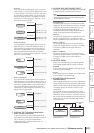
E Pair icon
This indicates the pairing status of two adjacent odd-
numbered/even-numbered channels.
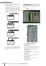
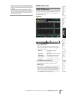
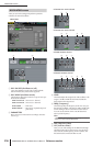
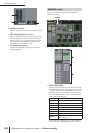
This screen contains meters that show the amount of gain
reduction produced by the gate/compressor for each input
channel (input channels 1–48, ST IN channels 1–4).
A GATE/COMP (Gate / Compressor)
These buttons select either Gate or Compressor as the
processor whose gain reduction amount is shown by
the meters. The display at the left will change accord-
ing to your selection.
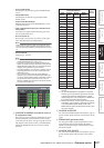
B Meters
These peak level meters indicate the amount of gain
reduction for each channel. The current fader value is
shown in the box below.
C Pair icon
This indicates the pairing status of two adjacent odd-
numbered/even-numbered channels.
4
5
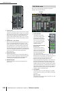
INPUT GR (Input Gain Reduction)
screen
INPUT GR
1
2
3