


16 Remote control
134 PM5D/PM5D-RH V2 / DSP5D Owner’s Manual Operating section
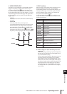
When controlling a continuously-variable parameter,
that parameter will be at its minimum value when the
voltage is at low level, and at its maximum value when
the voltage is at high level.
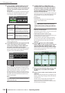
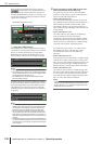
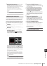
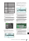
While the GPI screen is displayed, the GPI IN status
column of the GPI IN area will show a yellow bar
graph to indicate the approximate value of the voltage
being input to each port. (If the bar is not shown, the
voltage is grounded; if the bar is displayed all the way
to the right edge, the voltage is at high level.)
Hint
The voltage value at which the PM5D detects High or Low
level can be adjusted to suit the external controller (except for
external switches) you are using (
➥
p.135).
4
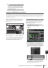
At the left edge of the FUNCTION column,
click the button to open the GPI IN PORT
ASSIGN window.
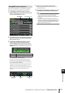
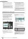
In the GPI IN PORT ASSIGN window you can select
the PM5D function that will be controlled by each GPI
IN port.
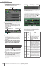
Use the FUNCTION column to select the type of func-
tion, and use the PARAMETER column to select the
optional parameters. You can select the following func-
tions and parameters.
After you have specified the function and parameter,
click the OK button.
Note
• If latched operation is selected, the port will change between
active/inactive each time a trigger is input from an external
switch. In this case, we recommend that you use a non-lock-
ing type of external switch.
• If unlatched operation is selected, the port will be active only
while the signal from the external switch stays at high level
or low level. In this case, we recommend that you use either
a non-locking or a locking type of external switch as appro-
priate for your situation.
FUNCTION PARAMETER PM5D operation
NO
ASSIGN
— No assignment
MONITOR
DIMMER ON
Switches the Dimmer func-
tion on/off
SOURCE =
[monitor
source name]
Switches the monitor source
MONO ON
Switches the Monitor section
[MONO] key on
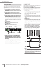
PARAMETER
column
FUNCTION columnGPI IN
status
POLARITY column
TALK-
BACK ON
LATCH
Switches the Talkback func-
tion on/off (latched operation)
UNLATCH
Switches the Talkback func-
tion on/off (unlatched opera-
tion)
CH ON-
LATCH
[channel
name]
Switches the channel on/off
(latched operation)
CH ON-
UNLATCH
[channel
name]
Switches the channel on/off
(unlatched operation)
FADER
LEVEL
[channel
name]
Modifies the fader value
(LEVEL parameter) accord-
ing to the voltage
SUR-
ROUND
PA N
FRONT-REAR
PAN [SEL]
Modifies the surround pan-
ning (front/rear) of the
selected channel according
to the voltage
LEFT-RIGHT
PAN [SEL]
Modifies the surround pan-
ning (left/right) of the selected
channel according to the volt-
age
FRONT-REAR
PAN [ODD]
Modifies the surround pan-
ning (front/rear) of the
selected odd-numbered
channel according to the volt-
age
LEFT-RIGHT
PAN [ODD]
Modifies the surround pan-
ning (left/right) of the selected
odd-numbered channel
according to the voltage
FRONT-REAR
PAN [EVEN]
Modifies the surround pan-
ning (front/rear) of the
selected even-numbered
channel according to the volt-
age
LEFT-RIGHT
PAN [EVEN]
Modifies the surround pan-
ning (left/right) of the selected
even-numbered channel
according to the voltage
USER
DEFINED
KEY
FUNCTION
[User Defined
key bank / key
number]
While the external input is
active, executes the same
operation as when the
selected User Defined key is
pressed
USER
DEFINED
KEY LED
[User Defined
key bank / key
number]
While the external input is
active, lights the LED of the
selected User Defined key
PEAK
HOLD ON
—
Switches the Peak Hold func-
tion on/off
OSCILLA-
TOR ON
Switches the Oscillator on/off
SOLO ON
Switches the Solo function
on/off
FUNCTION PARAMETER PM5D operation