


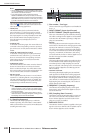

SYS/W.CLOCK function
224 PM5D/PM5D-RH V2 / DSP5D Owner’s Manual Reference section
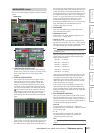
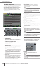
• PM5D-DCU5D — DSP5D-DCU5D — DSP5D
This system cascade-connects two DCU5D units and
two DSP5D units to the PM5D, adding two sets of 48
remotely located monaural inputs.
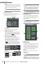
J CASCADE ENABLED/DISABLED
Turns the Cascade function on/off.
Note
• If you edit the parameters (
9
–
Q
) included in CASCADE
CONNECTION or power-cycle the unit, the cascade func-
tion will return to the Off state.
• If word clock becomes unlocked while machines are syn-
chronized (before cascade connection is enabled), the
operation of each machine may become unstable. If this
occurs, please power-cycle each machine.
• This setting will not be loaded for PM5D firmware V2.0 and
later.
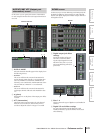
K DME CONTROL
This button accesses the DME CONTROL screen
(➥ p.199).
The following items
L–Q are shown only if you select
“PM5D-PM5D” or “PM5D-DCU5D — DCU5D-
PM5D”as the cascade-connection type. If you select a cas-
cade-connection that includes a DSP5D, the same settings
are made automatically, and the settings will be only for
viewing.
L CASCADE FROM (Source when cascade-
connected)
Select one of the following as the external device that is
sending audio signals to the PM5D via a cascade
connection.
M CASCADE IN PORT SELECT
Select one of the following as the port that will receive
the audio signals from the cascade-connected device.
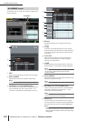
Hint
• If you select a choice other than CASCADE IN, the signal
from the slot will be assigned to the cascade input, and the
signal from the CASCADE IN connector will be assigned to
the corresponding slot input.
• The signal assigned from the CASCADE IN connector to the
slot input can be used as a patch source in the IN PATCH
screen.
• CASCADE IN
Up to 30 channels of audio signals can be received
from another PM5D via the rear panel CASCADE IN
connector. If PM5D is selected as the cascade source
(
L), control signals for parameter linkage will also be
transmitted and received.
• SLOT 4
Up to 16 channels of audio signals can be received via
input channels 1–16 of an I/O card installed in slot 4 of
the rear panel. If you choose this setting, the signals
from the CASCADE IN connector (channels 1–16) will
be assigned to channels 1–16 of the SLOT IN 4 port
instead.
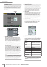
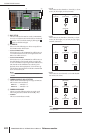
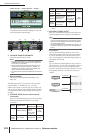
Display Source device
Available cas-
cade input port
Parame-
ter linkage
— Cascade disabled
CASCADE IN,
SLOT 3/4,
SLOT 1-4
[CH1-8], SLOT
1-4 [CH9-16]
Not
possible
PM5D or
PM5D+
DCU5D
another PM5D CASCADE IN Possible
*1
J
NL QP
M O K
DM2000
/02R96
Yamaha DM2000
or 02R96
CASCADE IN
Not
possible
MIXER
[30BUS]
A mixer other than
the above (maxi-
mum 30 bus)
SLOT 3/4,
SLOT 1-4
[CH1-8], SLOT
1-4 [CH9-16]
MIXER
[16BUS]
A mixer other than
the above (maxi-
mum 16 bus)
SLOT 4
*1. Linked parameters are specified in the CASCADE
screen.
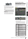
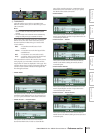
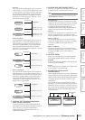
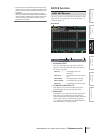
Display Source device
Available cas-
cade input port
Parame-
ter linkage
CASCADE IN
CH 1-16
SLOT 4
SLOT IN 1 (CH 1–16)
SLOT IN 2 (CH 1–16)
SLOT IN 3 (CH 1–16)
CH 1-16
SLOT 1-3
SLOT IN 4 (CH 1–16)
CASCADE IN
CH 1-16
16 channels
16 channels