


INPUT GATE/COMP function
290 PM5D/PM5D-RH V2 / DSP5D Owner’s Manual Reference section
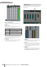
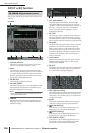
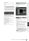
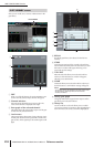
E Level meters
These meters indicate the
amount of gain reduction
(GR), the peak level before
(PRE) and after (POST)
the gate, and the peak level
of the key-in signal (KEY
IN) that causes the gate to
operate. If the signal clips,
the OVER segment will
light.
If stereo link is turned on
for the input channel (or if
a ST IN channel is
selected), level meters for
two channels are
displayed.
Hint
If GR METER ON/OFF LINK is turned on in the PREFER-
ENCE 1 screen (UTILITY function), the gain reduction meter
will not be displayed when the gate is off.
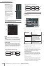
F Type
Indicates the type of the currently selected gate.
Hint
To change the gate type, use the INPUT GATE LIBRARY
screen to recall a library item that has a different type. You
cannot change only the gate type in this screen.
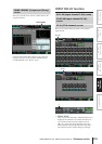
G STEREO LINK
This specifies whether parameter settings and gate
operation by a key-in signal will be linked (STEREO
LINK button on) for adjacent odd-numbered/even-
numbered input channels and the L/R channels of ST
IN channels, or not (STEREO LINK button off).
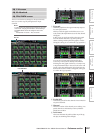
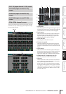
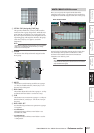
❏ Key-in signal flow when Link= On
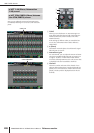
❏ Key-in signal flow when Link= Off
Note
Stereo Link is fixed at On for paired channels.
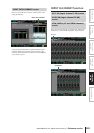
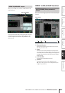
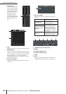
H Gate graph
This graph displays the approximate response of the
gate.
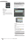
I KEY IN SOURCE
Here you can select one of the following as the key-in
signal that will be used. (If an input channel is selected,
its name will be displayed at the right.)
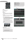
J FILTER
Select the type of filter to be applied to the selected key-
in signal, from the following types.
• HPF (High Pass Filter)
Passes the portion of the signal above the specified fre-
quency (the cutoff frequency), and cuts the portion
below. If you select this filter, use the knob at the right
to adjust the cutoff frequency (20 Hz–20 kHz).
• BPF (Band Pass Filter)
Passes only the specified frequency region (the band
pass frequency), and cuts the rest of the signal. If you
select this filter, use the knobs at the right to adjust the
band pass frequency (20 Hz–20 kHz) and Q (10.0–
0.10).
• LPF (Low Pass Filter)
Passes the portion of the signal below the specified fre-
quency (the cutoff frequency), and cuts the portion
above. If you select this filter, use the knob at the right
to adjust the cutoff frequency (20 Hz–20 kHz).
5
76
8
GR
THR
THR
LINK= ON
GR
Odd-numbered
channel key-in signal
Even-numbered
channel key-in signal
ATTACK
processing
ATTACK
processing
Detect
maximum
level
SELF PRE EQ
The pre-EQ signal of the currently
selected input channel
SELF POST EQ
The post-EQ signal of the currently
selected input channel
CH 1–48 POST EQ The post-EQ signal of the corre-
sponding input channel (however,
you can only choose channels
belonging to the same group,
within the seven groups CH1–8,
CH9–16, CH17–24, CH25–32,
CH33–40, CH41–48, and ST IN
1L/1R–4L/4R)
ST IN 1L/1R–4L/4R
POST EQ
MIX 21–24
The output signal of the corre-
sponding MIX channel immedi-
ately before the output patch
GR
THR
THR
LINK= OFF
GR
Odd-numbered
channel key-in signal
Even-numbered
channel key-in signal
ATTACK
processing
ATTACK
processing
Detect max-
imum level
Detect max-
imum level
L
J
9
K