


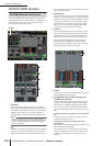

INPUT PATCH function
278 PM5D/PM5D-RH V2 / DSP5D Owner’s Manual Reference section
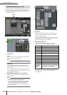
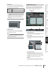
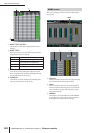
F PRESET
This button resets the input port → input channel
assignments to the following default settings.
G CLEAR ALL
This button clears all assignments of input ports to
input channels.
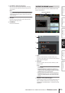
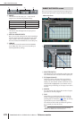
H VIRTUAL SOUNDCHECK
Here you can make settings for the virtual soundcheck
function, which temporarily switches the input patch-
ing. For details, refer to the explanation of the SYS/
W.CLOCK function MIXER SETUP screen (➥ p.221).
I LIBRARY
This button accesses the INPUT PATCH LIBRARY
screen (➥ p.283), where you can store/recall input
channel patch library settings.
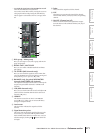
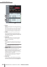
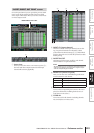
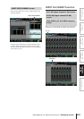
Here you can patch an input channel to an output port so
that the input signal will be output directly from that port.
A SELECTED PATCH
This indicates the name and number of the input chan-
nel at which the cursor is located, and the output port.
B CH (Input channel)
This is the number and name of the input channel
(input channel, ST IN channel) for assignment to an
output port. The channel number at which the cursor
is located will be highlighted. If you click the name, a
window will open allowing you to assign a name to the
channel.
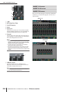
C ASSIGN
For each channel, this indicates the number of output
ports that are currently assigned.
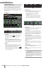
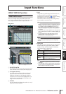
D Grid
This grid lets you patch input channels (vertical col-
umns) to output ports (horizontal rows). Currently-
patched grids are indicated by a symbol. By clicking
a grid location you can set/cancel patching.
The red lines at the left and top indicate the grid loca-
tion to which you move the cursor.
Hint
Operations in the grid are the same for all of the patching
screens. For details, refer to the Hint on p.277.
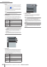
Channel Input port
Input channels 1–48 AD IN 1–48
ST IN channels 1–4 L/R AD STIN L/R
FX RTN channels 1–4 L/R FX OUT 1–4 L/R
6 7 98
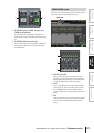
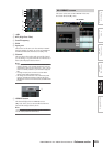
DIRECT OUT PATCH screen
DIRECT OUT PATCH
5
1
2
3 4