


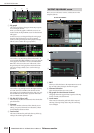

OUTPUT DCA/GROUP function
260 PM5D/PM5D-RH V2 / DSP5D Owner’s Manual Reference section
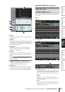
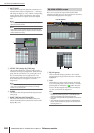
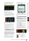
D MUTE SAFE
These buttons temporarily defeat the muted state of a
channel. When a button is displayed as “–”, clicking it
will change its display to “ON,” and the corresponding
output channel will be excluded from mute groups.
Clicking the button once again restores the original
state.
Note
Normally, Mute Safe operations can be performed indepen-
dently of the scene memory.
Hint
Mute groups 1–8 can be used with both input channels and
output channels. Both types of channel can exist in the identi-
cally-numbered mute group.
E SET BY CUE (Assign by [CUE] key)
This specifies whether the [CUE] key will be used to
make/cancel mute group assignments. While the mute
group SET BY CUE button is on, pressing the [CUE]
key of a channel that can be assigned to the corre-
sponding group will assign the channel to the group.
(Press the [CUE] key once again to cancel the
assignment.)
Hint
The SET BY CUE button can be turned on for only one mute
group. This is automatically turned off when you change
screens or turn off the power.
F CLEAR
This button clears all output channels assigned to that
mute group.
G DIRECT RECALL/MUTE MASTER
This is the same function as the DIRECT RECALL/
MUTE MASTER buttons located at the bottom of the
display (➥ p.165).
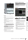
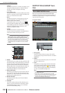
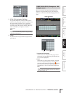
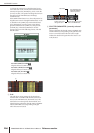
Here you can specify the output channels that will be
assigned to EQ link groups A–H. EQ parameters are linked
for channels belonging to the same group.
A EQ link group
These are the EQ link group numbers. The number
corresponding to the grid where the cursor is located is
highlighted.
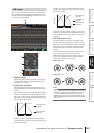
B Grid
This grid lets you assign output channels (horizontal
rows) to EQ link groups (vertical columns). Currently-
patched grids are indicated by a symbol. Move the
cursor to the desired grid and press the [ENTER] key
(or click) to set/cancel the assignment.
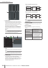
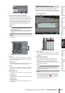
Hint
• The MIX channels and STEREO A/B channels can be
assigned only to EQ link groups A–F, and MATRIX chan-
nels can be assigned only to EQ link groups G/H.
• Grey areas in the grid indicate combinations that cannot be
assigned.
• Input channels and output channels use separate EQ link
groups. Output channels use groups A–H, and input chan-
nels use groups 1–8.
65
7
EQ LINK ASSIGN screen
EQ LINK ASSIGN
12