


PM5D/PM5D-RH V2 / DSP5D Owner’s Manual Reference section 309
Information shown
in the display
Function
menu
Global
functions
Output
functions
Input
functions
Appendices
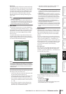
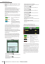
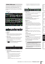
Here you can perform realtime control of surround pan-
ning for the two currently selected input channels.
A Channel selection
Select the two adjacent odd-numbered/even-num-
bered input channels (or ST IN channel L/R) that you
want to control. The names of these channels are dis-
played at the right.
B DIVERGENCE
These controls specify the proportion at which the sig-
nals are sent to each surround bus when the input
channel is positioned in the center. Depending on the
currently selected surround mode, the displayed
parameters will differ as follows.
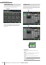
❏ If Surround Mode = 3-1ch/5.1ch
A knob for controlling the front
divergence is displayed. Use this
knob to specify the proportion (0–
100) at which a signal positioned
in the center will be sent to the
center bus (C) and the left/right
buses (L, R). With a setting of 0
the signal will be sent only to the
left/right buses, and with a setting
of 100 it will be sent only to the center bus. With a set-
ting of 50, the signal will be sent at the same level to the
left/right and center buses.
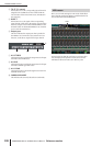
❏ If Surround Mode = 6.1ch
An F knob for controlling the front divergence and an
R knob for controlling the rear divergence are dis-
played. Use these two knobs to specify the proportion
(0–100) at which a signal positioned in the center will
be sent to the center buses (C, S, Bs) and the left/right
buses (L, R, Ls, Rs).
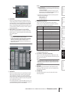
In 6.1ch mode, a LINK button
that links the front and rear diver-
gence is displayed between the F
knob and R knob. When you turn
the LINK button on, the F knob
value will be copied to the R knob,
and the F knob and R knob values
will be linked.
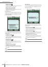
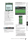
C LFE (Low Frequency Effect)
This adjusts the output level of the signal sent from the
input channel to the LFE (Low Frequency Effect) bus
for a subwoofer. You can use the ON/OFF button to
switch the signal sent from the input channel to the
LFE bus on/off.
The LFE knob and ON/OFF button are displayed only
when the surround mode is 5.1ch or 6.1ch.
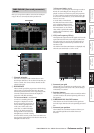
D Surround pan grid
This grid lets you control the surround panning, with
the listening point at the center. The current setting is
indicated by a O symbol.
E Position buttons
These buttons correspond to each surround bus. When
you click a button, the surround panning will move to
that position.
F SURROUND BUS ON/OFF buttons
These buttons are on/off switches for the signal sent
from the input channel to the corresponding surround
bus.
G Surround pan position
This indicates the coordinate locations of the O sym-
bol in the left/right direction and the front/rear
direction.
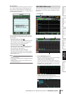
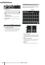
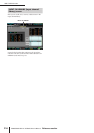
SURR PARAM (Surround parameter)
screen
SURR PARAM
1
2
3
4
5 6 7