


PM5D/PM5D-RH V2 / DSP5D Owner’s Manual Reference section 195
Information shown
in the display
Function
menu
Global
functions
Output
functions
Input
functions
Appendices
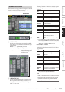
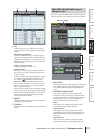
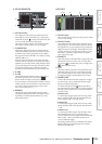
❏ GPI IN MONITOR
F GPI IN monitor
The voltage from the GPI IN port selected by the X-
AXIS field (
8) and Y-AXIS field (9) is respectively
indicated by a yellow in the X-axis (horizontal) and
Y-axis (vertical) dimensions of the graph.
The range of voltage variation used to determine the
active/inactive status is shown as a red rectangle.
G CALIBRATION
This button calibrates the range of voltage variation
used by the PM5D to determine active/inactive status,
so that the range will be appropriate for the voltages
being input from the GPI PORT. (For details on using
calibration ➥ p.135)
When you turn this button on, the range of voltage
variation will be temporarily cleared; the range will be
updated every time the GPI IN voltage changes. When
you turn this button off, the range of variation will be
memorized, and this range of variation will subse-
quently be used to determine the active/inactive state.
H X-AXIS
I Y-AXIS
These fields select the GPI IN port for which calibra-
tion will be performed. You can click the /
buttons at left and right to change the port.
If you are using a two-dimensional controller such as a
joystick, specify a port for both the X-axis and Y-axis. If
you want to perform calibration for only one direc-
tion, set one of the ports to “-----.”
J REVERSE
This button inverts the low/high level of the input,
changing the displayed direction of the graph. This is
equivalent to switching the POLARITY (3) of the
selected GPI IN port.
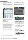
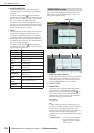
❏ GPI OUT
K GPI OUT port
These are the numbers of the GPI OUT ports for which
you can make settings.
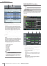
L GPI OUT status
This indicates the state of the output signal for the cor-
responding port. The L/H character indicates whether
the signal level is Low (the output level is grounded) or
High (the output level is high). The background color
is yellow when active, and gray when inactive. Use the
POLARITY (
M) field to select whether the signal is
active when low or high.
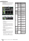
M POLARITY
Selects the polarity of the signal that is output when the
GPI OUT port becomes active. You can select either
Low Active (grounded when active) or High Active
(high level when active).
N TEST
This button tests the operation of each GPI OUT port.
While this button is on, the corresponding GPI OUT
port will temporarily become active, and a signal will
be output according to the POLARITY (
M) setting.
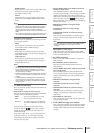
O FADER START
Indicates the channel of the fader assigned as a trigger
to each GPI OUT port, and the fader mode (trigger
detection method) of that fader.
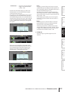
To edit the settings, click the button at the left to
open the GPI OUT PORT ASSIGN window, and select
the fader mode and channel. You can select the follow-
ing fader modes.
• FADER START
A control signal (trigger signal) 250 msec long will be
output when the fader of the selected channel moves
from –60 dB or below to exceed –60 dB.
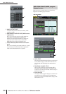
• FADER STOP
A control signal (trigger signal) 250 msec long will be
output when the fader of the selected channel reaches
–∞ dB.
• FADER TALLY
A control signal will be output when the fader of the
selected channel moves from –60 dB or below to
exceed –60 dB. This control signal will be held until the
fader reaches –∞ dB (or until that GPI OUT port
receives a different trigger).
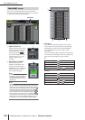
The setting of the GPI screen’s FADER START field is
linked with the GPI-related settings of the FADER
START screen (➥ p.196).
8
9
J
7
6
K L
M N O P Q