


PM5D/PM5D-RH V2 / DSP5D Owner’s Manual Operating section 157
19
Other functions
• SCENE STORE/EDIT
Scene store operations, store undo operations, title
editing, sorting
• CUE/SOLO LOGIC
Cue/Solo operations
• DIMMER ON/OFF
Dimmer effect (including talkback dimmer)
• PAGE CHANGE
Switching the display screen
• DCA FADER MODE
Switching the mode of the top panel FADER MODE
section
• ENCODER MODE
Switching the mode of the top panel ENCODER
MODE section
• PANEL/LCD BRIGHTNESS
BRIGHTNESS settings in the PREFERENCE 2 screen
(UTILITY function)
• INPUT METER POINT/OUTPUT METER POINT/
PEAK HOLD
Input channel / output channel metering point selec-
tion, and peak hold on/off
• DCA LEVEL/MUTE
DCA group 1–8 level, name, [CUE] key on/off opera-
tions, and [MUTE] key on/off operations
• MUTE MASTER
Mute group 1–8 on/off
Note
• Note that linking is enabled only if the LINK buttons for the
same item are turned on for both the cascade master unit
and the cascade slave unit.
• If you have cascade-connected three or more PM5D units in
a daisy-chain, you can also turn linking off for the cascade
master but on between the cascade slaves.
Hint
DCA and MUTE parameter values will be linked as soon as
linking is turned on. CUE/SOLO will be initialized as soon as
linking is turned on. Other parameters will be linked only when
that parameter is first operated after Link is turned on.
3
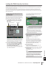
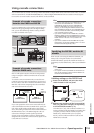
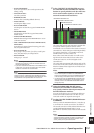
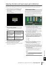
In the CASCADE I/O ASSIGN VIEW area, use
the CASCADE IN and CASCADE OUT ON/OFF
buttons to specify whether each bus will trans-
mit or receive audio signals to or from the
external cascade-connected device.
The CASCADE IN and CASCADE OUT ON/OFF but-
tons specify whether signals of each bus will be
transmitted to or received from the cascade-connected
external device. These settings are made independently
for each bus; MIX buses 1–24, STEREO A bus L/R,
STEREO B bus L/R, and CUE bus L/R.
Buses whose CASCADE IN button is on will receive
signals from the external device; buses whose CAS-
CADE OUT button is on will send signals to the
external device.
The CASCADE IN SOURCE fields indicate each of the
source buses. If the other cascade-connected device is a
PM5D or DSP5D, these assignments are fixed and can-
not be modified.
Note
• When two PM5D units are cascade-connected, signal trans-
mission and reception is enabled if the CASCADE OUT
button of the transmitting unit and the CASCADE IN button
of the receiving unit are both turned on for the same bus.
• If a device other than the PM5D/DSP5D is selected as the
other cascade-connected device, the transmission source
indication shown in the CASCADE IN SOURCE field will
change (
➥
p.227).
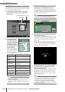
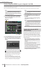
4
Using the PARAM LINK ON/OFF button
located in the CASCADE I/O ASSIGN VIEW
area, specify whether channel parameters will
be linked between machines.
You can specify this for every two adjacent odd-num-
bered/even-numbered channels. Turn this on if you
want each machine to output the same signal.
5
Set the CASCADE ENABLED/DISABLED button
to ENABLED.
When you click the DISABLED button, it may take up
to 10 minutes for cascade connection to be enabled.
The cascade connection will be enabled when the CAS-
CADE ENABLED/DISABLED button is set to
ENABLED on both the cascade master and the cascade
slave.
Note
If the word clock becomes unlocked while the machines are
synchronized (before cascade connection is enabled), the
operation of each machine may become unstable. If this
occurs, please power-cycle each machine.
CASCADE IN SOURCE area
CASCADE IN ON/OFF buttons
PARAM LINK buttons
CASCADE OUT ON/OFF buttons