


PM5D/PM5D-RH V2 / DSP5D Owner’s Manual Reference section 197
Information shown
in the display
Function
menu
Global
functions
Output
functions
Input
functions
Appendices
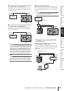
FADER STOP . . . . . GPI OUT port from which the
trigger is sent when the fader
reaches –∞ dB.
Note that the GPI-related settings you make in the
FADER START screen are linked with the FADER
START field of the GPI screen.
For example, if in the FADER START screen you spec-
ify different ports for the FADER START parameter
and FADER STOP parameter of a certain channel, the
FADER START field of the GPI screen will be assigned
to the corresponding channel (Fader Mode= FADER
START/FADER STOP) of those ports. (The opposite
also applies.)
If the same port is specified for the FADER START
parameter and the FADER STOP parameter, the GPI
screen FADER START field will be assigned to the
channel corresponding to that port (Fader Mode=
FADER TALLY). (The opposite is also true.)
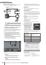
•MMC
An MMC command will be sent from the currently-
enabled MIDI port according to the fader operation of
the corresponding channel. (The MIDI transmit port is
selected in the MIDI SETUP screen.)
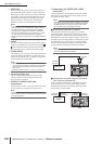
An MMC PLAY command is transmitted when the
fader changes from below –60 dB to –60 dB or higher,
and an MMC STOP command is transmitted when the
fader reaches –∞ dB.
If this output type is selected, you can use an option
parameter to specify the MMC device ID number (1–
127 or ALL).
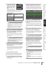
•RS422
An RS422 protocol command will be sent from the
RS422 REMOTE connector according to the fader
operation of the corresponding channel.
An RS422 protocol PLAY command is transmitted
when the fader changes from below –60 dB to –60 dB
or higher, and an RS422 protocol STOP command is
transmitted when the fader reaches –∞ dB.
D CLEAR ALL
Clears the Output Type field assignments of all
channels.
⇔
⇔