


PM5D/PM5D-RH V2 / DSP5D Owner’s Manual Reference section 333
Information shown
in the display
Function
menu
Global
functions
Output
functions
Input
functions
Appendices
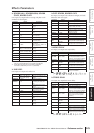
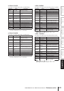
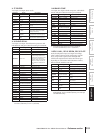
❏ ST REVERB
Two input, two output stereo reverb.
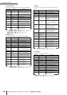
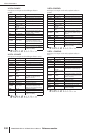
❏ M. BAND DYNA.
Two input, two output 3-band dynamics processor, with
individual solo and gain reduction metering for each band.
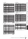
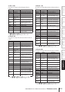
❏ M.BAND COMP
Two input, two output 3-band compressor, with individ-
ual solo and gain reduction metering for each band.
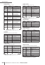
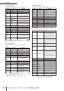
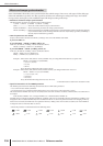
❏ REV-X HALL, REV-X ROOM, REV-X PLATE
Newly-developed two input, two output reverb algo-
rithm. Delivers dense and rich reverberation, smooth
decay, and provides a spaciousness and depth that
enhances the original sound. Choose from three types
depending on your location and needs; REV-X HALL,
REV-X ROOM, and REV-X PLATE.
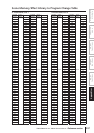
Parameter Range Description
REV TIME 0.3–99.0 s Reverb time
REV TYPE
Hall, Room, Stage,
Plate
Reverb type
INI. DLY 0.0–100.0 ms Initial delay before reverb begins
HI. RATIO 0.1–1.0 High-frequency reverb time ratio
LO. RATIO 0.1–2.4 Low-frequency reverb time ratio
DIFF. 0–10
Reverb diffusion (left–right reverb
spread)
DENSITY 0–100% Reverb density
E/R BAL. 0–100%
Balance of early reflections and
reverb (0% = all reverb, 100% =
all early reflections)
HPF
THRU, 21.2 Hz–
8.00 kHz
High-pass filter cutoff frequency
LPF
50.0 Hz–16.0 kHz,
THRU
Low-pass filter cutoff frequency
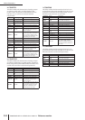
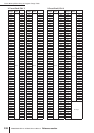
Parameter Range Description
LOW GAIN –96.0 to +12.0 dB Low band level
MID GAIN –96.0 to +12.0 dB Mid band level
HI. GAIN –96.0 to +12.0 dB High band level
PRESENCE –10 to +10
For positive values, the thresh-
old of the high band is low-
ered and the threshold of the
low band is increased. For
negative values, the opposite
will occur. When set to 0, all
three bands are affected the
same.
CMP. THRE –24.0 dB to 0.0 dB Compressor threshold
CMP. RAT 1:1 to 20:1 Compressor ratio
CMP. ATK 0–120 ms Compressor attack
CMP. REL 1 Compressor release time
CMP. KNEE 0–5 Compressor knee
LOOKUP 0.0–100.0 ms Lookup delay
CMP. BYP ON/OFF Compressor bypass
L–M XOVR 21.2 Hz–8.00 kHz Low/mid crossover frequency
M–H XOVR 21.2 Hz–8.00 kHz Mid/high crossover frequency
SLOPE –6 dB, –12 dB Filter slope
CEILING –6.0 dB to 0.0 dB, OFF
Specifies the maximum output
level
EXP. THRE –54.0 dB to –24.0 dB Expander threshold
EXP. RAT 1:1 to ∞:1 Expander ratio
EXP. REL
*1
*1. 6.0 ms–46.0 s (fs=44.1 kHz), 5.0 ms–42.3 s (fs=48 kHz),
3 ms–23.0 s (fs=88.2 kHz), 3 ms–21.1 s (fs=96 kHz)
Expander release time
EXP. BYP ON/OFF Expander bypass
LIM. THRE –12.0 dB to 0.0 dB Limiter threshold
LIM. ATK 0–120 ms Limiter attack
LIM. REL 1 Limiter release time
LIM. BYP ON/OFF Limiter bypass
LIM. KNEE 0–5 Limiter knee
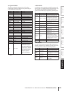
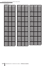
Parameter Range Description
LOW GAIN –96.0 to +12.0 dB Low band level
MID GAIN –96.0 to +12.0 dB Mid band level
HI. GAIN –96.0 to +12.0 dB High band level
L-M XOVR 21.2 Hz–8.00 kHz Low/mid crossover frequency
M-H XOVR 21.2 Hz–8.00 kHz Mid/high crossover frequency
SLOPE –6 dB, –12 dB Filter slope
CEILING –6.0 dB to 0.0 dB, OFF
Specifies the maximum output
level
LOOKUP 0.0–100.0 ms Lookup delay
LOW THRE –54.0 dB to 0.0 dB Low band threshold level
MID THRE –54.0 dB to 0.0 dB Mid band threshold level
HI. THRE –54.0 dB to 0.0 dB High band threshold level
RATIO 1:1 to 20:1 Compression ratio
ATTACK 0–120 ms Compressor attack time
CMP. REL
*1
*1. 6.0 ms–46.0 s (fs=44.1 kHz), 5.0 ms–42.3 s (fs=48 kHz),
3 ms–23.0 s (fs=88.2 kHz), 3 ms–21.1 s (fs=96 kHz)
Compressor release time
KNEE 0–5 Compressor knee
BYPASS ON/OFF Bypasses the compressor
Parameter Range Description
REV TIME
0.47–46.92 s
*1
*1. These values are for when the effect type is REV-X HALL and the
ROOM SIZE=28. The range will differ depending on the effect type
and ROOM SIZE setting.
Reverb time
INI. DLY 0.0–120.0 ms Initial delay before reverb begins
HI. RATIO 0.1–1.0 High-frequency reverb time ratio
LO. RATIO 0.1–2.4 Low-frequency reverb time ratio
LO.FREQ 22.0 Hz–18.0 kHz
Frequency point for LO.RATIO
setting
DIFF. 0–10
Reverb diffusion (left–right reverb
spread)
ROOM
SIZE
0–28
Size of room
DECAY 0–53 Gate closing speed
HPF
THRU, 22.0 Hz–
8.00 kHz
High-pass filter cutoff frequency
LPF
1.00 kHz–18.0 kHz,
THRU
Low-pass filter cutoff frequency