


PM5D/PM5D-RH V2 / DSP5D Owner’s Manual Reference section 221
Information shown
in the display
Function
menu
Global
functions
Output
functions
Input
functions
Appendices
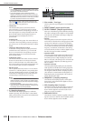
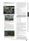
Here you can make settings that apply to the entire PM5D
system.
A +48V MASTER (DSP5D only)
This is the master phantom power (+48V) switch for
INPUT jacks 1–48 and ST IN jacks 1–4. If this switch is
off, the +48V button shown in the display will be
disabled.
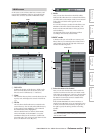
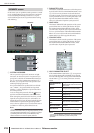
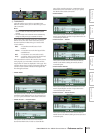
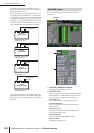
B VIRTUAL SOUNDCHECK
This temporarily switches the input signals without
affecting the scene memory (input patching). For
example, this allows you to perform a sound check
using pre-recorded material played back by a DAW
connected to a slot, instead of the analog input mate-
rial received via the INPUT jacks. When you click the
button located at the left, the VIRTUAL SOUND-
CHECK SETUP window will appear, allowing you to
assign a replacement port for each port. To enable
these settings, click the ON/OFF button located at the
right.
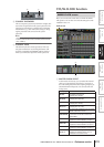
For each port, you can specify a port that will be substi-
tuted virtually. You cannot assign the same port to more
than one port. If you assign a previously-assigned port
to a different port, the patch will be turned off (shown in
gray) for the port whose assignment was taken away. If a
slot is exchanged with the CASCADE IN connector, the
cascade bus number will be displayed in black on a yel-
low background in the slot port number display area. In
the example shown above, slots 1 and 2 are assigned to
AD IN 1–32, so you’ll be able to perform a sound check
using pre-recorded audio received at slots 1 and 2
instead of the analog inputs to the INPUT jacks.
By clicking the PRESET button, you can return the set-
tings of the VIRTUAL SOUNDCHECK SETUP
window to their factory-set state.
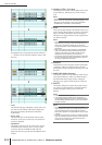
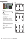
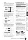
C PAIR MODE
Select one of the following two methods by which
input channels will be paired.
• HORIZONTAL PAIR
If this button is on, input channels of adjacent num-
bers (1/2, 3/4 ...) will be paired.
• VERTICAL PAIR
If this button is on, input channels of different layers
that share the same fader (1/25, 2/26 ...) will be paired.
This setting lets you use the faders of the INPUT chan-
nel strip to control up to 24 pairs (48 channels).
Hint
The graphic below the buttons will change according to the
pair mode you select.
When you switch from horizontal pair mode to verti-
cal pair mode, new numbers will be assigned to the
input channels as follows.
Channel 1 → no change
Channel 2 → Channel 25
Channel 3 → Channel 2
Channel 4 → Channel 26
:
Channel 47 → Channel 24
Channel 48 → no change
(If you again switch back to horizontal pair mode, the
channels will return to their previous number.) How-
ever, please note that this simply means the input
channel that was previously called “channel 2” is now
called “channel 25”; the name and parameter settings
of that channel have not changed.
In the various screens of the display (except for the
TRACKING RECALL screen and the FADER VIEW
screen), switching the pair mode will only change the
displayed numbers; the arrangement of the input chan-
nels will not change.
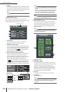
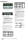
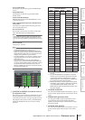
D PAN NOMINAL POSITION
Here you can specify whether a signal will be at nomi-
nal level when panned to center, or at nominal level
when panned far left or far right. Choose one of the fol-
lowing two settings. You can choose independently for
monaural channels and paired channels.
• CENTER
The signal will be at nominal level (+0 dB) when
panned to the center, and will rise +3 dB when panned
to far left or far right.
•L ↔ R
The signal will be at nominal level (+0 dB) when
panned to far left or far right, and will decrease
–3 dB when panned to the center.
Hint
The current setting is also shown by the graph below the
buttons.
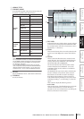
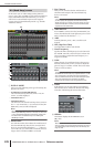
MIXER SETUP screen
MIXER SETUP
1
3
2
4