


19 Other functions
154 PM5D/PM5D-RH V2 / DSP5D Owner’s Manual Operating section
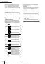
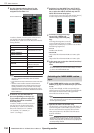
• For machine ID #1
• For machine ID #2
• For machine ID #3
3
While the machine ID number LEDs are lit
(within five seconds), you can repeatedly press
the mode switch to cycle through machine ID
#1 → #2 → #3 → #1 → #2 → #3.
Note
The machine ID number LED indication will return to the nor-
mal display when you have not pressed the mode switch for
five seconds or more.
❏ Making settings from DSP5D Editor
1
Synchronize DSP5D Editor with the DSP5D
itself.
2
In the Mixer Setup window, use Cascade Con-
nection to specify the machine ID number.
Note
For details, refer to the DSP5D Editor Owner’s Manual.
Here we will explain the basic settings needed when cas-
cade-connecting the PM5D and DSP5D, and when
cascade-connecting two PM5D units bi-directionally.
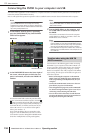
❏ Cascade-connecting the PM5D and
DSP5D
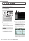
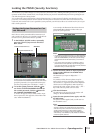
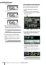
1
In the DISPLAY ACCESS section, repeatedly
press the [SYS/W.CLOCK] key until the MIXER
SETUP screen appears.
2
In the CASCADE CONNECTION area located at
the bottom of the screen, click the TYPE
SELECT button to access the CASCADE TYPE
SELECT window.
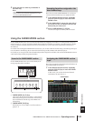
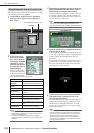
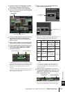
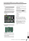
3
According to the DSP5D or DCU5D that is con-
nected, select the appropriate connection
type, and click the OK button to close the
window.
According to the type you selected, a connection dia-
gram is shown in the CASCADE CONNECTION field,
and cascade settings such as ports will be made
automatically.
Hint
For details on each connection type, refer to p.223.
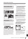
OUT
OUT
TX RX TX RX
IN
IN
OUT
OUT
TX RX TX RX
IN
IN
OUT
OUT
TX RX TX RX
IN
IN
Basic settings for cascade connection
MIXER SETUP
CASCADE CONNECTION areaTYPE SELECT