


PM5D/PM5D-RH V2 / DSP5D Owner’s Manual Operating section 43
5
Input channel operations
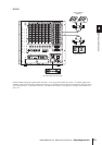
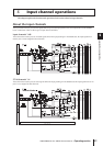
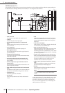
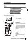
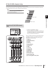
AD IN section
The AD IN section AD-converts the signals that are input from the rear panel INPUT jacks 1–48 and ST IN jacks 1–4, and
sends them to the input patch section. The structure of this section differs between the PM5D model and the PM5D-RH
model.
PM5D model
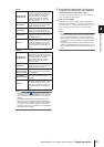
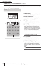
A [+48V ON/OFF] switch
If this switch is on, +48V is supplied to the condenser
mic or direct box connected to the INPUT jack 1–48.
B [PAD] switch
If this switch is on, the input level is attenuated by
26 dB.
C [GAIN] knob
Adjusts the input sensitivity of the input channel. The
range of adjustment is –34 dBu to +10 dBu (when the
PAD switch is on) or –60 dBu to –16 dBu (when the
PAD switch is off).
D [PEAK]/[SIGNAL] LED
The [SIGNAL] LED will light when the input level
reaches 14 dB below nominal level (i.e., 34 dB below
clipping level). The [PEAK] indicator will light when
the signal reaches 3 dB below clipping level.
E [INSERT ON/OFF] switch
This switch enables/disables the INSERT IN/OUT jack
located on the rear panel.
F ST IN [GAIN] knob
Adjusts the input sensitivity of the ST IN channel. The
range of adjustment is –34 dBu to +10 dBu.
G ST IN [PEAK]/ST IN [SIGNAL] LED
The ST IN [SIGNAL] LED will light when the input
level of the ST IN channel reaches 14 dB below nomi-
nal level (34 dB below clipping level). The ST IN
[PEAK] indicator will light when the signal reaches
3 dB below clipping level.
H [LAMP DIMMER] knob
This adjusts the brightness of the lamp connected to
the LAMP connector.
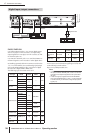
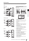
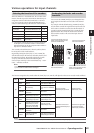
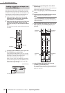
PM5D model
PM5D-RH model
DSP5D
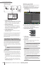
Items in the AD IN section
5
3
2
1
4
7
8
6