


2 Top, front, and rear panels
16 PM5D/PM5D-RH V2 / DSP5D Owner’s Manual Operating section
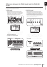
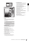
This chapter explains the names and functions of each part of the PM5D/DSP5D. Details for each
section of the top panel are explained in subsequent chapters of this operating section; refer to the
appropriate chapter for more information.
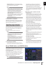
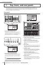
Top panel
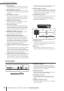
A AD IN section (PM5D model)
In this section you can adjust the sensitivity of the ana-
log signals being input from the rear panel INPUT
jacks 1–48 and ST IN jacks 1–4, and switch pad, insert,
and phantom power (+48 V) on/off (➥ p.43).
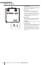
B AD IN section (PM5D-RH model)
This area indicates the presence, peak level, and phan-
tom power (+48V) on/off status of the input signal
from rear panel INPUT jacks 1–48 and ST IN jacks 1–
4.
Hint
For the PM5D-RH model, input sensitivity and phantom power
on/off are controlled by operations in the display (
➥
p.44).
C INPUT channel strip section
This section controls the principal parameters for input
channels 1–48 (➥ p.45).
D FADER FLIP/ENCODER MODE section
Here you can select the parameters controlled by the
faders/encoders of the INPUT channel strip (
3)
(➥ p.48).
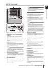
E MIX section
This section controls the on/off status and send level of
the signals sent from input channels to MIX buses, and
adjusts the master level of the MIX channels (➥ p.57).
F MATRIX section
This section controls the send level of the signals sent
from MIX channels to MATRIX buses, and adjusts the
master level of the MATRIX channels (➥ p.63).
G SELECTED CHANNEL section
In this section you can view and control the mix
parameters for the currently selected input channel or
output channel (➥ p.65).
H Meter section
This section contains peak level meters that indicate
the input levels of input channels and the output levels
of output channels and cue monitoring, as selected by
key operations (➥ p.108).
2 Top, front, and rear panels
1
(PM5D model)
2
(PM5D-RH model)
4 5
3
6 8
7