


METER function
232 PM5D/PM5D-RH V2 / DSP5D Owner’s Manual Reference section
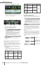
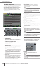
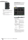
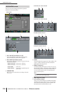
D Meters
These peak level meters indicate the input level of each
channel. The current fader value is shown in the box
below.
If clipping occurs at any point PRE ATT, POST EQ,
POST GATE, POST COMP, INSERT IN, or POST
FADER, the ∑ segment will light.
E Pair icon
This indicates the pairing status of two adjacent odd-
numbered/even-numbered channels.
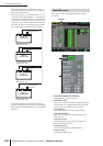
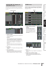
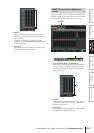
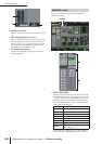
This screen contains meters that show the output level of
output channels (MIX channels 1–24, MATRIX channels
1–8, STEREO A/B channels), MONITOR (L/R/C), and
CUE (L/R).
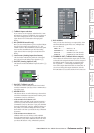
A METERING POINT
Select one of the following as the point at which the
output level will be detected.
PRE EQ . . . . . . . . . . Immediately before the EQ
PRE FADER . . . . . . Immediately before the fader
POST FADER . . . . . Immediately after the fader
POST ON . . . . . . . . Immediately after the [ON] key
POST DELAY . . . . . Immediately after the internal
delay (of an output channel)
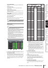
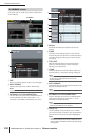
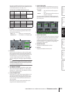
B CUE METERING POINT
Select one of the following as the point at which the
output level of the cue signal will be detected.
PRE DELAY . . . . . . Immediately before the internal
delay (of a monitor/cue
channel)
POST DELAY . . . . . Immediately after the internal
delay (of a monitor/cue
channel)
C PEAK HOLD
If this button is on, the peak level of each meter will be
held. When you turn this button off, the peak level
indication that had been held will be cleared. Peak hold
will be cleared when you change the metering point
(
1). This button is linked with the [PEAK HOLD] key
in the METER section of the top panel.
4
5
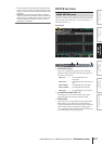
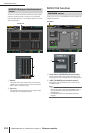
OUTPUT METER screen
OUTPUT METER
1 2 3