


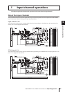

4 Connections and setup
38 PM5D/PM5D-RH V2 / DSP5D Owner’s Manual Operating section
Word clock connections and settings
This section explains the word clock settings required in order to send or receive digital audio between the PM5D/DSP5D and
an external digital device.
When digital audio signals are being sent or received
between multiple devices, the devices must process the
audio signals at the matching timing. For example if the
audio signal processing is not synchronized, the signals will
not be transmitted correctly and unpleasant noise will
occur even if both devices are set to the same sampling
frequency.
The signal used to synchronize digital audio signal process-
ing is called “word clock.” Normally, one device transmits
a reference word clock signal, and the other devices receive
this word clock signal and synchronize to it. (The transmit-
ting device is called the “word clock master” and the
receiving devices are called “word clock slaves.”)
The word clock can be synchronized between the PM5D/
DSP5D and external devices in either of two ways; you can
send/receive a word clock signal by itself, or use the clock
data that is included in a digital audio signal.
The WORD CLOCK IN/OUT connectors on the rear
panel of the PM5D (front panel for the DSP5D) are used to
send/receive a word clock signal by itself. In general, word
clock connections can be made in either of the following
two ways.
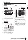
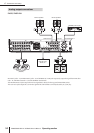
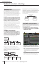
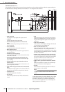
Using daisy-chain connections
In this method, the signal is distributed sequentially; the
WORD CLOCK OUT connector of the first device is con-
nected to the WORD CLOCK IN connector of the second
device, and so on. Turn all of the PM5D’s 75Ω ON/OFF
switches ON. On the DSP5D, this is fixed at 75Ω ON. This
method is not recommended for large systems.
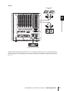
Using a word clock distribution box
In this method, a special word clock distribution box is
used to distribute the signal from the word clock master to
multiple word clock slaves. Turn ON all of the 75Ω ON/
OFF switches.
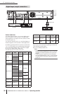
If an external device does not have WORD CLOCK IN/
OUT connectors, the clock data included in the digital
audio signal is used. In this case, both the digital audio sig-
nal and the clock data are sent from the DIGITAL OUT
jack of the word clock master to the DIGITAL IN jack of
the word clock slave.
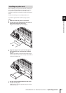
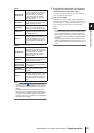
When digitally connecting the PM5D/DSP5D to an exter-
nal device, you must select the source that will be the word
clock master for the system.
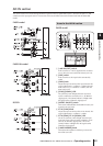
1
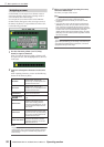
Repeatedly press the [SYS/W.CLOCK] key of
the DISPLAY ACCESS section until the WORD
CLOCK screen appears.
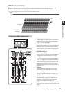
In this screen you can select the master clock, and
check the input signal synchronization status for each
slot or jack.
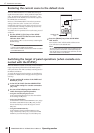
Note
When you switch the word clock source, noise may occur due
to loss of synchronization. You must lower the level of your
monitoring equipment before you perform the following
operation.
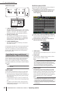
Use the MASTER CLOCK SELECT area located in the
upper part of the screen to select the master clock
source. You can choose one of the following sources.
About word clock
WC IN
(BNC)
WC OUT
(BNC)
WC OUT (BNC)
WC IN
(BNC)
WC IN
(BNC)
WC OUT
(BNC)
75Ω ON/OFF= ON
75Ω ON/OFF= ON 75Ω ON/OFF= ON 75Ω ON/OFF= ON
Word clock
master
Device A
Word clock
slave
Device B
Word clock
slave
Device C
Word clock
slave
WC OUT
(BNC)
WC IN (BNC) WC IN (BNC) WC IN (BNC) WC IN (BNC)
75Ω ON/OFF= ON
75Ω ON/OFF= ON 75Ω ON/OFF= ON75Ω ON/OFF= ON 75Ω ON/OFF= ON
Word clock
master
Device A
Word clock
slave
Word clock
distribution box
Device B
Word clock
slave
Device C
Word clock
slave
Device D
Word clock
slave
DIGITAL
OUT
DIGITAL
IN
Digital audio signal
+
Clock data
Device A
Word clock
master
Device B
Word clock
slave
Selecting the word clock master
WORD CLOCK MASTER CLOCK SELECT area