


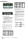
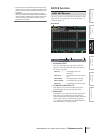

SYS/W.CLOCK function
228 PM5D/PM5D-RH V2 / DSP5D Owner’s Manual Reference section
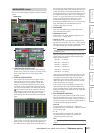
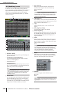
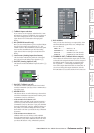
In this screen you can make settings such as phantom
power (+48V), gain, and HPF for each of the internal head
amps (PM5D-RH model and DSP5D only), or for each
channel of an external head amp device that supports
remote control via the dedicated protocol (e.g., Yamaha
AD8HR or AD824).
A DISPLAY MODE
Select one of the following as the type of head amp dis-
played in the screen.
• INTERNAL HA (PM5D-RH/DSP5D)
The internal head amp channels (AD IN 1–48, AD
STIN 1–4) will be displayed.
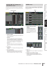
• EXTERNAL HA 1-4
• EXTERNAL HA 5-8
The channels of an external head amp device (ID num-
ber= 1–4, or ID number= 5–8) connected via the [HA
REMOTE] connector will be displayed.
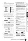
Hint
Up to eight external devices can be daisy-chained to the
PM5D’s [HA REMOTE] connector. In this case, an ID number
(1–8) is automatically assigned to each device, starting from
the device that is connected directly to the PM5D’s [HA
REMOTE] connector.
B Model name
For each ID number, this indicates the model name of
the external head amp device that is connected. If no
device is connected this will indicate “-----”. However
even in this case, you will be able to make the same set-
tings as when a Yamaha AD8HR is connected.
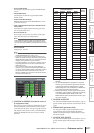
C Slot/Channel
Here you can view/select the slot and channels to
which the audio output of the external head amp
device is connected.
Note
If an external head amp device is connected to a PM5D slot,
you must specify the appropriate slot/channels manually.
Please note that if you specify an incorrect setting, the input
channel HA indication in screens such as the IN HA screen
may differ from the actual state.
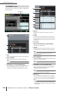
D +48V MASTER
If an AD8HR is connected via the [HA REMOTE] con-
nector, this indicates the master phantom power on/off
status. (Otherwise, this indicates “---”.)
E +48V
Switches phantom power (+48V) on/off for each
channel.
F HPF (High Pass Filter)
Turns the HPF on/off for each channel.
G Cutoff frequency
Specifies the HPF cutoff frequency for each channel of
the AD8HR. Move the cursor to the box, and turn the
[DATA] encoder to adjust the cutoff frequency in a
range of 20–600 Hz.
H GAIN
Adjusts the gain for each channel. Move the cursor to
the knob, and turn the [DATA] encoder to adjust the
gain in a range of –62 dB to +10 dB. The current value
is shown in the box below.
Note
The PAD will be switched on or off internally when the gain of
the PM5D-RH internal head amp is adjusted between –14 dB
and –13 dB. Keep in mind that noise may be generated if
there is a difference between the Hot and Cold output imped-
ance of the external device connected to the INPUT
connector/ST IN connector when using phantom power.
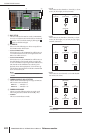
I GANG
If this button is on, the gain settings of two adjacent
odd-numbered/even-numbered channels will change
in tandem, maintaining the current offset value.
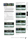
J LIBRARY
This button displays the HA LIBRARY screen
(➥ p.230).
Note
When an external head amp device is connected for the first
time, the settings on the external head amp device are used. If
you subsequently recall a HA library item, the HA library set-
tings are used.
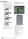
HA (Head Amp) screen
HA
1
2
5
6
9
7
8
3
4
J