


MIDI REMOTE function
202 PM5D/PM5D-RH V2 / DSP5D Owner’s Manual Reference section
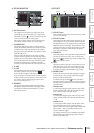
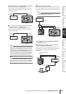
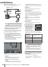
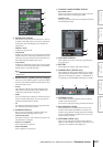
2 Connection using a DCU5D unit
You can use an Ethernet cable to connect the DSP5D and
DME series via a DCU5D digital cabling unit.
Note
The DSP5D must be connected via the CASCADE OUT (RJ-
45) connector.
❏ Initiating communication between the
PM5D and the DME series unit
To select the port used for audio signal transmission/recep-
tion between the PM5D and the DME series unit, and to
initiate communication, proceed as follows.
1
Connect the PM5D and the DME series unit.
2
In the DISPLAY ACCESS section, press the
[MIDI/REMOTE] key several times to access the
DME CONTROL screen.
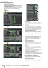
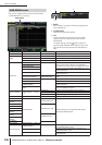
3
In the component selection area at the upper
left of the screen, select SETUP.
A screen like the following will appear.
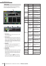
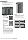
The SETUP screen contains the following items.
A CONNECT
This button initiates or terminates the connection
between the PM5D and the DME series unit.
B MIDI PGM CHANGE (MIDI program
change)
If this button is on, a program change message will be
transmitted to the DME via the I/O card or via the
CASCADE IN/OUT connectors when a scene is
recalled on the PM5D. This allows scenes to be recalled
on the DME in tandem with scene recall operations on
the PM5D.
C INPUT PORT
Here you can select the PM5D port that will receive
audio signals from the DME.
D MONITOR PORT
Here you can select the PM5D port that will receive
monitor signals from the DME. Since this monitor sig-
nal is sent to the PM5D’s CUE bus, the DME’s monitor
function can be controlled from the PM5D just like the
PM5D’s own cue function (EXTERNAL CUE
function).
E MIXER SETUP (show the MIXER SETUP
screen)
This button displays the SYS/W.CLOCK function
MIXER SETUP screen.
F OUTPUT PORT
Here you can select the PM5D port that will output
audio signals to the DME.
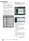
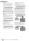
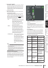
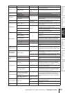
4
In the INPUT PORT area
located at the lower left
of the screen, select the
PM5D port that will
receive audio signals from
the DME series unit.
The types of port that can be
selected here will depend on
the port that is currently selected for cascade input
(MIXER SETUP screen CASCADE IN PORT SELECT
field), as follows.
Note
• You cannot switch the cascade input port setting from the
DME CONTROL screen. If necessary, click the MIXER
SETUP button to access the MIXER SETUP screen (SYS/
W.CLOCK function), and change the port you will use for
cascade input.
• Depending on the type of cascade connection, the DSP5D
port will indicate only the items that can be selected: ---,
SLOT1-2, CASCADE IN (D-SUB), or CASCADE OUT (RJ-
45).
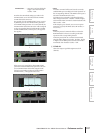
5
In the MONITOR PORT field, select the PM5D
port that will receive monitor signals from the
DME series unit.
The following ports can be selected.
---- . . . . . . . . . . . . . . . . . .No assignment
SLOT1-1–SLOT4-16 . . .The desired port of slot 1–4
CASCADE 1–32 . . . . . . .CASCADE IN ports 1–32
DSP5D
CASCADE IN
HUB
DCU5D
POWER
DME series
CASCADE
OUT connector
CASCADE
IN connector
to CASCADE IN (D-SUB)
connector
CASCADE OUT
(D-SUB) connector
CASCADE OUT
(RJ-45) connector
CASCADE
IN (RJ-45)
connector
1 5
4 6
2
3
Setting in the CAS-
CADE IN PORT
SELECT field (MIXER
SETUP screen)
Items available in the INPUT
PORT field
CASCADE IN ----, SLOT1–SLOT4
SLOT4 ----, CASCADE IN, SLOT1–SLOT3
SLOT3/4 ----, CASCADE IN, SLOT1–SLOT2
SLOT1-4 [CH1-8] ----, CASCADE IN
SLOT1-4 [CH9-16] ----, CASCADE IN