


PM5D/PM5D-RH V2 / DSP5D Owner’s Manual Reference section 239
Information shown
in the display
Function
menu
Global
functions
Output
functions
Input
functions
Appendices
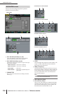
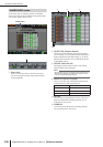
the USE AS STEREO BUS button or the USE AS CEN-
TER BUS button is turned on in the STEREO B section
of the MIXER SETUP screen (➥ p.222).
❏ If the USE AS STEREO BUS button is on
❏ If the USE AS CENTER BUS button is on
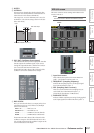
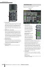
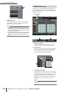
B DEFINE
If “DEFINE” is selected in the MONITOR SOURCE
section, you can choose the signal that will be moni-
tored from the following.
MIX 1–24 . . . . . . . . MIX bus 1–24 output signal
MATRIX 1–8. . . . . . MATRIX bus 1–8 output signal
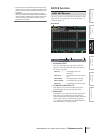
C DIMMER
When you turn this button on, the level of the signal
being monitored will be temporarily attenuated. The
knob adjusts the amount of attenuation that will occur
when the button is on. The range of adjustment is
–96 dB to 0 dB. While this button is on, the DIMM
indicator will appear in the upper right of the display.
Hint
You can also use an external switch connected to the GPI IN
connector to switch the dimmer on/off. To do so, assign the
MONITOR DIMMER ON function to the GPI IN port to which
the switch is connected. (
➥
p.194).
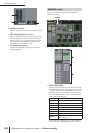
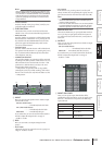
D TALKBACK DIMMER
This adjusts the amount by which the monitor signal
will be attenuated when talkback is on. The range of
adjustment is –96 dB to 0 dB. The talkback on/off sta-
tus is shown in the box below.
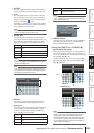
E CUE INTERRUPTION
If this button is on, the cue/solo signal will also be out-
put from the MONITOR OUT jacks while the Cue/
Solo function is active. During this time, the monitor
source selected in the MONITOR SOURCE section
will be disabled.
If this button is off, the cue/solo signal will never be
output from the MONITOR OUT jacks.
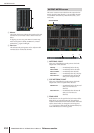
F MONITOR MODE
Here you can select one of the following two ways in
which the signal will be output from the MONITOR
OUT jacks.
STEREO . . . . The L/R channels will be output in
stereo.
MONO . . . . . The L/R channels will be mixed, and
output in monaural.
The status of these two buttons is linked with on/off
operations of the [MONO] key in the MONITOR sec-
tion of the panel.
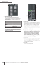
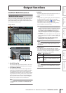
G MONITOR INSERT
This area shows the input jacks (and input channels of
the digital I/O card) that are inserted into the MONI-
TOR OUT L/C/R channels. The input level of the
inserted signal is shown by the level meter at the right.
If GEQ or EFFECT is inserted, the corresponding
information is shown here.
H INSERT ON/OFF
This button enables/disables insertion.
I PATCH
Displays the INSERT PATCH screen.
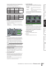
Monitor
source
LRC
ST A STEREO A L STEREO A R
—ST B STEREO B L STEREO B R
LCR — —
Monitor
source
LRC
ST A STEREO A L STEREO A R —
ST B — —
STEREO B L
LCR STEREO A L STEREO A R
3 4
5
6
7
8
9