


PM5D/PM5D-RH V2 / DSP5D Owner’s Manual Operating section 153
19
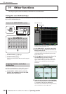
Other functions
Using cascade connections
You can share buses by cascade-connecting a PM5D and DSP5D, multiple PM5D units (maximum of four units), or a PM5D
with an external mixer (Yamaha DM2000/02R96, etc.). When multiple PM5D/DSP5D units are cascade-connected, opera-
tions such as scene store/recall, cue/solo, and dimmer can also be linked.
Up to two DSP5D units can be cascade-connected to one
PM5D unit. By going through a DCU5D digital cabling
unit, you can also utilize long-distance routing via Ether-
net cable. For details, refer to p.31.
Here we will explain cascade connections and operation,
using an example in which two PM5D units are cascade-
connected.
To cascade-connect two PM5D units, connect the CAS-
CADE IN connectors and CASCADE OUT connectors of
the two units to each other. This allows the MIX bus, STE-
REO bus, and CUE bus output signals to be transmitted
and received between the two units.
If you want operations such as scene store/recall and cue/
solo to be linked between the two PM5D units, specify one
unit as the cascade master and the other as the cascade
slave. (This setting is made in the SYS/W.CLOCK function
MIXER SETUP screen.) The PM5D assigned as the cas-
cade master will output control signals (operational
signals) via its CASCADE IN connector, and the PM5D
assigned as the cascade slave will receive these signals via its
CASCADE OUT connector.
Hint
• If you want to daisy-chain two to four PM5D units (i.e., con-
nect the first unit’s CASCADE OUT
→
second unit’s
CASCADE IN, and the second unit’s CASCADE OUT
→
third unit’s CASCADE IN. Up to four units can be con-
nected.), you should assign the PM5D located last in the
chain (the PM5D connected only via its CASCADE IN con-
nector) as the cascade master, and the remaining PM5D
units as cascade slaves (
➥
p.226).
• If you want to cascade-connect a PM5D with a Yamaha
DM2000 or 02R96, connect the CASCADE OUT connector
of the DM2000/02R96 to the CASCADE IN connector of the
PM5D. However in this case, it is not possible to link
operations.
• If you want to cascade-connect the PM5D with any other
external mixer, use I/O cards installed in slots 1–4 to send
and receive the audio signals (
➥
p.224).
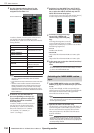
When cascade-connecting the PM5D and DSP5D, you
must specify a unique ID number for each machine
(PM5D and DSP5D). Specify the machine ID number as
#1 (PM5D), #2 (first DSP5D unit), and #3 (second DSP5D
unit).
Note
• The PM5D’s machine ID number is fixed at #1, so you don’t
need to set it.
• For a system in which only DSP5Ds are connected in cas-
cade, set the machine ID number of the first DSP5D to #1,
and set the second DSP5D to #2.
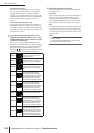
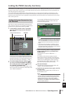
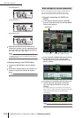
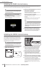
❏ Making settings on the DSP5D itself
1
Power-on the DSP5D, and press the mode
switch located on the rear panel.
2
Between one and three of the front panel IN/
OUT [TX]/[RX] LEDs will light, corresponding
to the machine ID number (1–3).
One LED (OUT [TX]) is lit to indicate machine #1 (a
system consisting of only the DSP5D), two LEDs (OUT
[TX]/[RX]) are lit to indicate machine #2 (the first
DSP5D unit), and three LEDs (OUT [TX][RX]
IN[TX]) are lit to indicate machine #3 (the second
DSP5D unit) is selected.
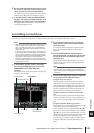
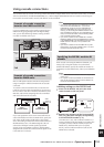
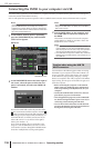
Example of cascade connections
between the PM5D and DSP5D
Stage
FoH
DSP5D DSP5D
DCU5D
POWER
CASCADE
CASCADE
OUT
OUT
OUT
IN
IN
IN
IN
OUT
IN
CASCADE IN CASCADE IN
Ethernet CAT5
Ethernet
CAT5
OUT
PM5D
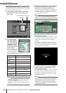
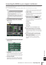
Example of cascade connections
between PM5D units
PM5D A
CASCADE
IN
CASCADE
OUT
CASCADE
IN
CASCADE
OUT
PM5D B
Audio
signals of
units A+B
Audio
signals of
units A+B
(cascade master) (cascade slave)
Specifying the DSP5D’s machine ID
number
FAN
HIGH LOW
POWER
FAN
HIGH LOW
POWER
Mode switch