


PM5D/PM5D-RH V2 / DSP5D Owner’s Manual Reference section 207
Information shown
in the display
Function
menu
Global
functions
Output
functions
Input
functions
Appendices
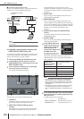
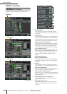
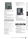
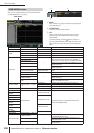
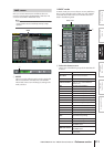
J UPPER PART DISPLAY
These buttons select the item that is shown in the cen-
ter right (to the right of the scene memory indication)
of the upper part of the display (the constantly dis-
played area).
• PRESENT TIME
Indicates the present time.
• TIME CODE
Indicates the internal time code being generated by the
PM5D, or the time code being received from an exter-
nal device. This is the same as the time code shown in
the SCENE function EVENT LIST screen.
• CASCADE/Fs
Indicates the master/slave status when using a cascade
connection, and the sampling frequency at which the
PM5D system is currently operating.
Hint
You can also cycle through these choices by clicking in this
display section.
K NAME DISPLAY ([NAME] indicator display)
Choose one of the following as the content that will be
shown by the [NAME] indicators of the INPUT chan-
nel strip and DCA strip.
• NAME
The indicators will show the names assigned to the
input channels / DCA groups in the NAME screen
(INPUT PATCH function). (➥ p.282)
• PORT
For input channels, the indicators will show the name
of the currently assigned port. For DCA groups, the
indicators will show the ID number.
•ID
For both input channels and DCA groups, the indica-
tors will show the fixed ID number.
L WARNING DISPLAY
Here you can select whether a warning will be dis-
played when the following problems occur.
• TIME CODE DROP
When time code (LTC, MTC) being received from an
external device is dropped.
• DIGITAL I/O ERROR
When a DIO error is detected.
• MIDI I/O ERROR
When a MIDI error is detected.
M CHANNEL NAME NUMERIC DISPLAY
• ENCODER VALUE
When you operate an encoder (pan setting), the name
display will switch to indicating that value.
• FADER VALUE
When you operate a fader, the name display will switch
to indicating that value.
N SOFTWARE VERSION
This indicates the version of the unit’s operating soft-
ware (firmware).
O BATTERY
This indicates the voltage of the internal battery.
P POWER SUPPLY (DSP5D only)
This indicates the status of the DSP5D’s power supply.
This will indicate “INTERNAL” if the DSP5D is oper-
ating on its internal power supply, or “EXTERNAL” if
it is operating on the PW800W external power supply.
Q INTERNAL CLOCK
This indicates the year/month/day (DATE) and time
(TIME) of the internal clock.
If you want to change the setting, click the SET button.
R BACKGROUND COLOR
This specifies the screen background color for each
machine. If the PM5D and DSP5D are cascade-con-
nected, having a different background color will make
it easier to distinguish the machines when you switch
between them for control.
S NETWORK (DSP5D only)
Here you can make network settings used when the
DSP5D’s [NETWORK] connector is connected to your
computer via an Ethernet cable (➥ p.159).
J
K
L
M
N
O
P
Q R S