


PM5D/PM5D-RH V2 / DSP5D Owner’s Manual Operating section 49
5
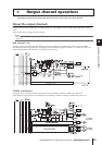
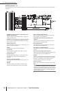
Input channel operations
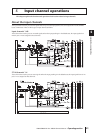
Various operations for input channels
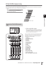
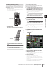
When the PM5D is in the default state, the encoders of the
INPUT channel strip and ST IN/FX RTN channel strip are
assigned to control send levels to MIX buses 1–24. How-
ever you can use the various ENCODER MODE keys to
select one of the following as the function of the encoders.
The currently selected function is shown by the key that is
lit and by the encoder mode indicator.
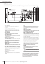
Repeatedly pressing the [PAN] key or [ALT LAYER] key
will alternate between the function selected by that key and
the MIX bus send level. Repeatedly pressing the [GAIN/
ATT] key will alternate between the following three
choices; input sensitivity to the internal head amp → atten-
uator → MIX bus send level.
Hint
If the FADER section [FLIP] key is on, the functions controlled
by the encoders and faders will be exchanged.
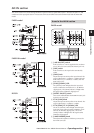
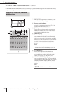
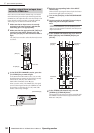
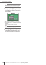
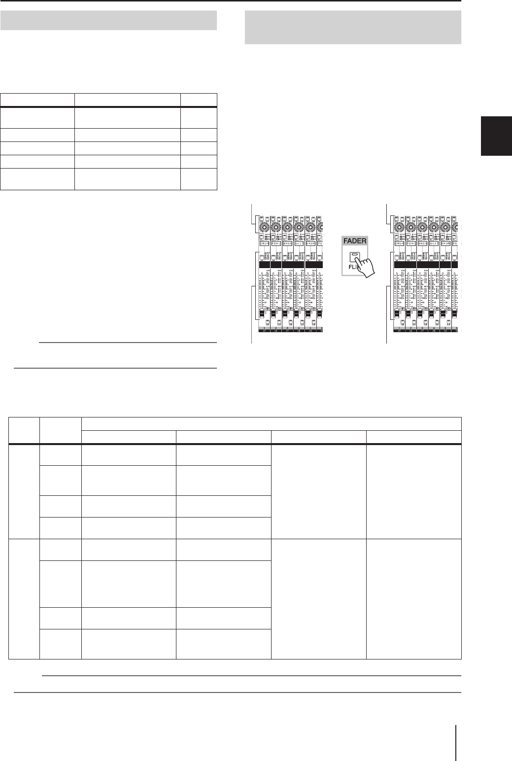
You can use the FADER [FLIP] key to exchange the func-
tions assigned to the faders and encoders of the channel
strip.
For example with the default setting (FADER [FLIP] key
off), the faders control the input channel input levels, and
the encoders control the send levels to the MIX buses. If
you then press the FADER [FLIP] key to make the LED
light, the faders will control the send levels to the MIX
buses and the encoders will control the input channel
input levels.
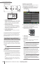
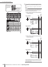
The function assigned to the controls when the [FLIP] key is on (LED lit) will depend on the current encoder mode as follows.
Note
The DCA channel strip and STEREO A/B channel strip are not affected by the on/off status of the [FLIP] key.
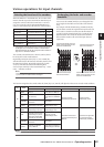
Key Encoder function Display
MIX SEND SELECT
[1]–[24] keys
Send levels to MIX buses 1–24 1–24
[PAN] key Pan (balance) Pn
[GAIN/ATT] key Head amp input sensitivity HA
[GAIN/ATT] key Attenuator At
[ALT LAYER] key
Input level for the currently un-
selected layer
*1
*1. In the INPUT channel strip, the CH 1-24 layer and the CH
25-48 layer are in a “front/rear” relation. In the ST IN/FX
RTN channel strip, the ST IN 1-4 layer and the FX RTN 1-4
layer are in a “front/rear” relation.
AL
Selecting the function of the encoders
Exchanging the fader and encoder
functions
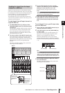
➠
Control the channel input
level and on/off status
Control the channel input
level and on/off status
Control the send level and on/off
status of the signal sent from the
channel to the MIX buses
Control the send level and on/off
status of the signal sent from the
channel to the MIX buses
[FLIP]
key
Encoder
mode
Function of each control
Encoder ENCODER [ON] key Fader CH [ON] key
Off
MIX
SEND
Send level from channel to
MIX bus
On/off status of signal sent
from channel to MIX bus
Channel (currently
selected layer) input level
Channel (currently
selected layer) on/off
PA NPan (balance)
On/off status of signal sent
from channel to STEREO
bus
GAIN/ATT
Head amp input sensitivity
/ attenuator
No function
ALT
LAYER
Channel (currently un-
selected layer) input level
Channel (currently un-
selected layer) on/off
On
MIX
SEND
Channel (currently
selected layer) input level
Channel (currently
selected layer) on/off
Send level from channel
(currently selected layer) to
MIX bus
On/off status of signal sent
from channel (currently
selected layer) to MIX bus
PA N
Pan of the signal sent from
channels (of the currently
selected layer) to paired
MIX buses (invalid if MIX
channels are not paired)
Channel (currently
selected layer) on/off
GAIN/ATT
Head amp input sensitivity
/ attenuator
No function
ALT
LAYER
Send level from channel
(currently un-selected
layer) to MIX bus
On/off status of signal sent
from channel (currently un-
selected layer) to MIX bus