


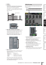
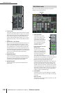
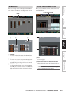
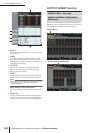

OUTPUT PATCH function
244 PM5D/PM5D-RH V2 / DSP5D Owner’s Manual Reference section
F LIBRARY button
This button accesses the OUTPUT PATCH LIBRARY
screen (➥ p.247), where you can store/recall patch
library settings for output channels.
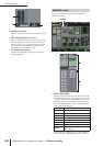
Hint
• The signal from immediately after the delay and immedi-
ately before the output port attenuation will be sent to output
ports you patch in this screen. Subsequently, in the case of
SLOT OUT and 2TR OUT, the specified output port attenua-
tion will be applied respectively.
• The rear panel MATRIX OUT jacks 1–8, and STEREO OUT
jacks A/B always output the signal of the corresponding out-
put channel. They are not affected by the settings in this
screen.
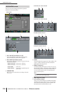
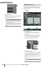
In this screen you can patch the input/output ports into
which external devices will be inserted. Select the output
port in the left side of the screen, and the input port in the
right side of the screen.
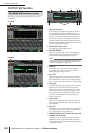
A SELECTED PATCH
This indicates the number and name of the output
channel at which the cursor is located in the grid.
B Insert in/out
This indicates the input/output ports that are patched
as insert in/out for the output channel at which the
cursor is located. If multiple ports are assigned for
insert-out, only the first port is displayed.
C CH (Output channel)
This area shows the numbers and names of the output
channels (MIX channels, MATRIX channels, STEREO
A/B channels, MONITOR L/R/C channels). The chan-
nel number at which the cursor is located will be
highlighted. When you click the name area, a window
will appear, allowing you to assign a name to the
channel.
Note
On the DSP5D, this is unavailable for the MONITOR L/R/C
channels.
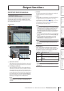
6
INSERT PATCH screen
INSERT PATCH
21
6
3
45