


19 Other functions
150 PM5D/PM5D-RH V2 / DSP5D Owner’s Manual Operating section
2
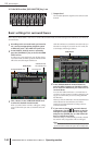
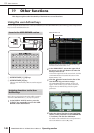
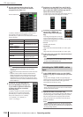
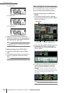
Use the channel selection boxes for the
desired layer (A–F) to select the channel
assigned to each fader 1–8.
To select a channel, move the cursor to the box and
turn the dial. The channel will blink; press the
[ENTER] key to confirm. You can choose from the fol-
lowing channels.
Hint
• If an input channel or a DCA fader 1–8 is selected, the chan-
nel name is displayed immediately below the channel
selection box.
• Input channels and output channels can coexist in the same
layer.
• Channels of each machine cascade-connected with the
DSP5D are assigned to the channels that show the corre-
sponding machine ID (#1–#3). Channels of the currently
selected machine are assigned to the channels for which a
machine ID is not shown. However, MONITOR and CUE are
fixed at PM5D (#1).
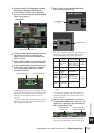
3
As desired, use the MACHINE ID
box corresponding to the layer (A–
F) you want to operate to select the
machine that will be controlled
from the panel.
To select a machine, move the cursor and
turn the [DATA] encoder and press the
[ENTER] key to confirm. The machines
that can be selected are “#1” (PM5D),
“#2” (DSP5D), “#3” (DSP5D), or
“STAY” (no change).
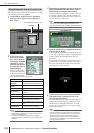
4
As desired, use the INPUT box and ST IN/FX
RTN box for the layer (A–F) you want to oper-
ate to select the INPUT channel strip and ST
IN/FX RTN channel strip layers.
To select a layer, move the cursor and turn the [DATA]
encoder and press the [ENTER] key to confirm.
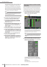
5
As desired, change the assign-
ment of the STEREO A/B
channel strip (fader and [ON]
key).
To change the assignment, move the
cursor and turn the [DATA] encoder
and press the [ENTER] key to confirm. You can select
the following assignments.
• ST A/B
STEREO A/B channels
• MONITOR
Output level from the MONITOR OUT L/R/C jacks
• CUE
Output level from the MONITOR OUT L/R/C jacks
6
In the same way, assign the channel/machine/
layer for other layers.
Hint
The settings of the FADER MODE section are not saved in
the scene. If desired, you can save these settings on a mem-
ory card as DCA FADER MODE data.
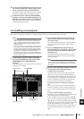
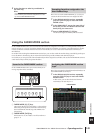
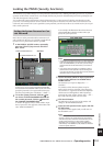
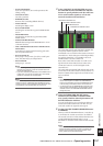
1
In the FADER MODE section, use the FADER
MODE [A]–[F] keys to select the layer you want
to use.
The key LED will light, and the corresponding layer
will become active. If input channels are assigned to the
DCA faders, the channel names will appear in the
name indicators of the DCA strip.
Hint
You can also switch layers from within the FADER ASSIGN
screen. This screen also shows the values of the DCA faders
and their approximate positions.
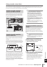
2
Operate the faders of the DCA strip.
The level of the corresponding channels will change. If
a channel assigned to a DCA fader is paired (or if one
side of a stereo channel is assigned), the level of the
other paired channel (or the other side of the stereo
channel) will follow.
Note
If a FADER MODE [A]–[F] key is on, the DCA channel strip
[MUTE] keys can be used as [ON] keys of the corresponding
channels. The [CUE] keys can also be used as [CUE] keys for
the corresponding channels.
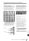
Item Selected channel
CH 1–CH 48 Input channel 1–48
STIN1L/STIN1R–STIN4L/
STIN4R
ST IN channel 1–4 L or R
FXRTN1L/FXRTN1R–
FXRTN4L/FXRTN4R
FX RTN channel 1–4 L or R
MIX 1–MIX 24 MIX channel 1–24
MTRX1–MTRX8 MATRIX channel 1–8
DCA1–8 DCA fader 1–8
MONITOR
Output level from the MONI-
TOR OUT L/R/C jacks
CUE
Output level from the CUE
OUT jacks
---- Fader disabled
STAY No change
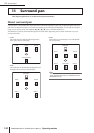
Channel selection box
Switching the FADER MODE section
layer