


MIDI REMOTE function
196 PM5D/PM5D-RH V2 / DSP5D Owner’s Manual Reference section
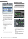
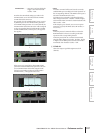
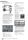
P USER DEFINED KEYS
This area indicates the User Defined keys that are
assigned as triggers to each GPI OUT port, and their
operations.
To edit the setting, click the button at the left to
open the GPI OUT PORT ASSIGN window; from the
list, select the User Defined key bank (A–D) and num-
ber (1–25), and how the trigger signal will be
transmitted. As the transmission method for the trig-
ger signal, you can select either Latch (switch between
active/inactive each time the key is pressed) or Unlatch
(active only while the key is pressed).
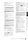
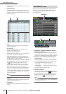
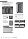
Q TALLY
This area indicates the state of other Tally output func-
tions assigned as triggers to each port. When you
execute the corresponding operation on the PM5D, a
control signal will be output from the corresponding
GPI OUT port. This control signal will be held until
you defeat the above operation (or until that GPI OUT
port receives a different trigger).
To edit the settings, click the button at the left to
open the GPI OUT PORT ASSIGN window, and select
one of the following functions.
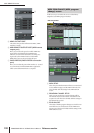
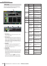
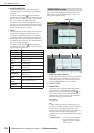
Here you can make settings for the Fader Start function
which lets you use input channel faders to control GPI
OUT ports or external devices.
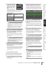
A INPUT CH (Input channel)
This area shows the number and name of the channels
(input channels, ST IN channels) for which you can
make settings. When you click a line to select it, that
line will be highlighted in the center of the list.
B OUTPUT TYPE
C PARAMETER
Indicates the type of signal that will be output when
you operate the corresponding fader, and option
parameters for it. To edit the setting, click the but-
ton at the left of the OUTPUT TYPE field to open the
FADER START ASSIGN window. You can select the
following output types and parameters.
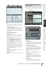
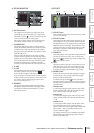
• NO ASSIGN
No assignment.
• GPI
A trigger will be sent to the specified GPI OUT port
according to the fader operation of the corresponding
channel, and a control signal will be output. (The
polarity of the control signal will be as specified by the
settings in the GPI screen.) If this output type is
selected, you can choose from the following two option
parameters.
FADER START . . . GPI OUT port from which the
trigger is sent when the fader
changes from below –60 dB to
exceed –60 dB.
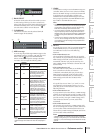
Function PM5D operation
NO ASSIGN No assignment
POWER ON The PM5D’s power is turned on
SOLO ON [SOLO] key is turned on
GPI IN 1 FUNC-
TION
The function assigned to GPI IN port 1
becomes active
GPI IN 2 FUNC-
TION
The function assigned to GPI IN port 2
becomes active
GPI IN 3 FUNC-
TION
The function assigned to GPI IN port 3
becomes active
GPI IN 4 FUNC-
TION
The function assigned to GPI IN port 4
becomes active
PREVIEW ON
SCENE MEMORY section [PREVIEW]
key is turned on
CUE ON [INPUT
ONLY]
Input channel [CUE] key is turned on
CUE ON [DCA
ONLY]
DCA [CUE] key is turned on
CUE ON [OUT-
PUT ONLY]
Output channel [CUE] key is turned on
CUE ON Any [CUE] key is turned on
FADER START screen
FADER START
1 2 3 4