


19 Other functions
156 PM5D/PM5D-RH V2 / DSP5D Owner’s Manual Operating section
through which audio signals will be transmitted to and
received from the cascade-connected external device.
If “PM5D” or “DM2000/02R96” are selected as the
other cascade-connected device, only “CASCADE IN”
can be selected for the CASCADE IN PORT SELECT
field. In the CASCADE OUT PORT SOURCE SELECT
field, you can choose from the output channels of slots
1–4 as well as “CASCADE OUT” (➥ p.225).
Hint
If you choose a setting other than “CASCADE OUT” in the
CASCADE OUT PORT SOURCE SELECT field, the same
signal will be output from both the specified slot/channel and
from the CASCADE OUT connector.
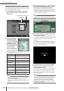
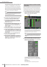
❏ Cascade slave (bi-directional cascade
connections between PM5D units)
1
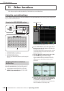
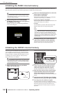
In the DISPLAY ACCESS section, repeatedly
press the [SYS/W.CLOCK] key to access the
MIXER SETUP screen.
2
In the CASCADE CONNECTION area located at
the bottom of the screen, click the TYPE
SELECT button to access the CASCADE TYPE
SELECT window.
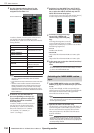
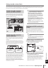
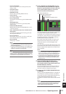
3
Select “PM5D - PM5D” as the connection type,
and click the OK button to close the window.
4
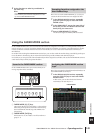
In the CASCADE MODE area at the lower part
of the screen, select “SLAVE”. In addition, turn
on the BI-DIRECTION button located immedi-
ately below it.
5
Select “PM5D” in the CASCADE FROM field
and in the CASCADE TO field.
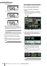
6
Make sure that “CASCADE IN” is selected in
the CASCADE IN PORT SELECT field, and “CAS-
CADE OUT” is selected in the CASCADE OUT
PORT SOURCE SELECT field.
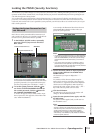
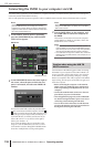
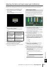
Here we will explain how to select the buses used for the
cascade connection, specify the items that will be linked,
and enable the cascade connection. Perform the following
steps on both the cascade master and cascade slave units.
1
In the DISPLAY ACCESS section, repeatedly
press the [SYS/W.CLOCK] key until the CAS-
CADE screen shown below appears.
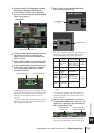
In this combination you can enable/disable buses used
for transmission/reception in the cascade connection,
and select the operations that will be linked when mul-
tiple PM5D units are cascade-connected.
Note
In the case of a system that is cascade-connected to the
DSP5D, the system will always operate as though the CAS-
CADE LINK area’s LINK button is on; this setting cannot be
changed.
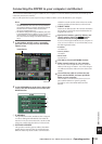
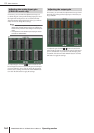
2
In the CASCADE LINK area at the left of the
screen, turn on the buttons for the operations
that you want to be linked.
The settings of the CASCADE LINK area select the
operations that will be linked when multiple PM5D
units are cascade-connected. You can select the follow-
ing items.
• SCENE RECALL
Scene recall operations / Recall undo operations
Selecting the buses used for cascade
connection
CASCADE