


MON/CUE function
238 PM5D/PM5D-RH V2 / DSP5D Owner’s Manual Reference section
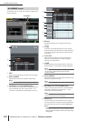
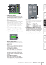
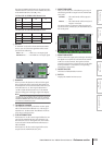
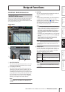
E Output level meter
Indicates the output level of 2TR OUT DIGITAL jacks
1–3.
F SRC (Sampling Rate Converter)
These are on/off and output frequency select switches
for the sampling rate converters built into 2TR OUT
DIGITAL jacks 1–3. As the output frequency you can
select either 44.1 kHz or 48 kHz. The on/off button
selects either ON or THROUGH (off).
G Fs (Sampling frequency)
This indicates the sampling frequency at which the
PM5D is operating.
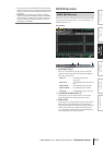
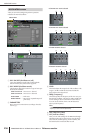
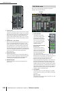
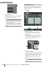
Here you can make settings and perform operations
related to monitoring.
A MONITOR SOURCE
Selects the source that will be monitored from the L/R/
C MONITOR OUT jacks. You can select one from 2TR
IN A1/A2, 2TR IN D1–D3, or DEFINE, and also simul-
taneously select one from STEREO A/B or LCR. These
buttons are linked with the various keys of the MONI-
TOR section in the top panel.
If a monitor source indicated by (*) is selected, the sig-
nal that is output will change depending on whether
5
6
7
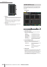
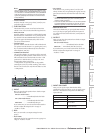
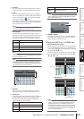
2TR IN A1 2TR IN ANALOG jack 1 input signal
2TR IN A2 2TR IN ANALOG jack 2 input signal
2TR IN D1 2TR IN DIGITAL jack 1 input signal
2TR IN D2 2TR IN DIGITAL jack 2 input signal
2TR IN D3 2TR IN DIGITAL jack 3 input signal
STEREO A STEREO A channel output signal (*)
STEREO B STEREO B channel output signal (*)
LCR LCR channel output signal (*)
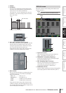
DEFINE
The signal selected in the DEFINE section
(
2) of this screen
MONITOR screen
MONITOR
1
2