


PM5D/PM5D-RH V2 / DSP5D Owner’s Manual Reference section 245
Information shown
in the display
Function
menu
Global
functions
Output
functions
Input
functions
Appendices
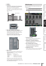
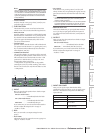
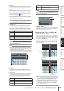
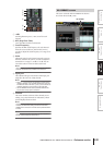
D ASSIGN
For each output channel, this indicates the number of
output ports that are currently assigned as insert-out.
E Grid
For each output channel (vertical column), this grid
lets you can patch one or more output ports (horizon-
tal row) to be used as insert-outs. Currently-patched
grids are indicated by a symbol.
By clicking a grid location you can set/cancel patching.
The red lines at the left and top indicate the grid loca-
tion to which you move the cursor.
Hint
Operations in the grid are the same for all of the patching
screens. For details, refer to the Hint on p.243.
F Output port
From the top, this area indicates the type of output
port, the ID number, the output channel number, and
the number of output channels assigned. The follow-
ing types of output port can be patched as insert-out.
Note
On the DSP5D, you can choose from OMNI OUT 1-24, SLOT
OUT 1-4 (SLOT OUT 3-4 is the CASCADE OUT connector),
FX IN 1-8, and GEQ IN 1-20.
Hint
If you select FX IN as an insert-out, the output of the same
internal effect will automatically be selected as the insert-in. If
you select GEQ IN, the output of the same GEQ module will
automatically be selected as the insert-in.
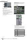
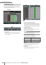
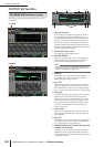
G ASSIGN
For each input channel, this indicates the number of
input ports that are currently assigned as insert-in.
H Input port
From the top, this area indicates the type of input port,
the ID number, the input channel number, and the
number of input channels assigned. The following
types of input port can be selected.
Note
On the DSP5D, you can choose from OMNI OUT 1-24, SLOT
OUT 1-4 (SLOT OUT 3-4 is the CASCADE OUT connector),
FX IN 1-8, and GEQ IN 1-20.
I LIBRARY button
This button accesses the OUTPUT PATCH LIBRARY
screen (➥ p.247), where you can store/recall patch
library settings for output channels.
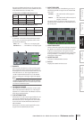
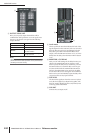
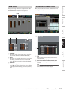
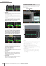
❏ Using the [SHIFT] key + CURSOR [√]/
[®] to move the cursor
When operating from the panel, you can move the cur-
sor from the right side of the screen to the left side (or
vice versa) by holding down the [SHIFT] key and using
the CURSOR [√]/[®] keys.
To quickly move the cursor in or out of the grid, hold
down the [SHIFT] key and press the CURSOR [√]/
[®]/[π]/[†] keys.
Note
To enable an insert-in assigned to an output channel in this
screen, you must turn on the ON/OFF button for the corre-
sponding output channel in the INSERT POINT screen
(OUTPUT PATCH function). (
➥
p.246) However, the insert-
out is always on, regardless of the state of the ON/OFF but-
ton. An exception to the above is that if you insert GEQ, its
insert-in will automatically be on.
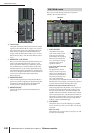
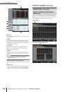
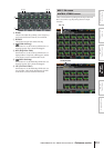
MIX OUT MIX OUT jacks 1–24
SLOT OUT
Output channels of an I/O card installed in slots
1–4
FX IN L/R inputs of internal effects 1–8
GEQ IN Inputs of internal GEQ modules 1–20
2TR OUT L/R channels of 2TR OUT DIGITAL jacks 1–3
AD IN INPUT jacks 1–48
AD ST IN ST IN jacks 1–4 L/R
SLOT IN
Input channels of an I/O card installed in slots
1–4
FX OUT L/R outputs of internal effects 1–8
8
7
GEQ OUT Outputs of GEQ modules 1–20
2TR IN
L/R channels of 2TR IN DIGITAL jacks 1–3 and
2TR IN ANALOG jacks 1/2
9
➠
[SHIFT] key
+
CURSOR [®] key
Cursor
Cursor will move