


PM5D/PM5D-RH V2 / DSP5D Owner’s Manual Reference section 165
[DATA] encoder to directly switch between “SEND”
and “MASTER.”
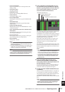
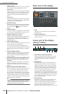
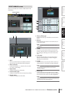
D Encoder/Fader mode
Indicates the parameters that are assigned to the
encoders/faders of the input channel strip.
The encoders can be assigned to MIX SEND 1–24,
GAIN, ATT, PAN/BAL, LEVEL, or REMOTE. The fad-
ers can be assigned to LEVEL, MIX SEND 1–24, or
REMOTE. For both the encoders and the faders, for
parameters other than REMOTE, you can move the
cursor and turn the [DATA] encoder to switch them
directly.
If you select LEVEL for the encoders, the faders will be
flipped; the most recently selected of the MIX SEND 1–
24 parameters will be assigned to the faders. Similarly,
the faders will also be flipped if you select MIX SEND
1–24 for the faders; the LEVEL parameter will be
assigned to the encoders.
E INPUT CH (Input channel) layer
This shows the layer that is selected for the input chan-
nel strip in tandem with the [CH 1-24]/[CH 25-48]
keys located in the input channel strip of the panel or
the FADER MODE [A]–[F] keys of the FADER MODE
section. (If the MIDI REMOTE layer is selected, this
will indicate REMOTE 1-24.) For layers other than
MIDI REMOTE, you can move the cursor and turn the
[DATA] encoder to select them directly.
F FADER MODE
This is linked with the FADER MODE section on the
panel, and indicates the function that is assigned to the
faders of the DCA strip. You can also move the cursor
and turn the [DATA] encoder to change this directly.
G ST IN/FX RTN (ST IN channel / Effect
return) layer
This shows the layer that is selected for the ST IN chan-
nel strip in tandem with the [ST IN] key / [FX RTN 1-
4] key located in the ST IN channel strip of the panel or
the FADER MODE [A]–[F] keys of the FADER MODE
section. (If the MIDI REMOTE layer is selected, this
will indicate REMOTE 25-28. If a layer of a machine
other than the input channel layer is selected, the
machine ID number is also shown.) For layers other
than MIDI REMOTE, you can move the cursor and
turn the [DATA] encoder to select them directly.
H DIRECT RECALL/MUTE MASTER
This switches between the following two choices as the
function of the [1]–[8] keys in the SCENE MEMORY
section of the panel.
• DIRECT RECALL
Keys [1]–[8] of the SCENE MEMORY section will
directly recall the scene that was assigned in the SCENE
screen.
• MUTE MASTER
Keys [1]–[8] of the SCENE MEMORY section will
switch mute groups 1–8 on/off.
I USER DEFINED KEY BANK
Indicates the currently selected bank of User Defined
keys. You can also move the cursor and turn the
[DATA] encoder to change this directly.
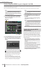
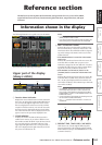
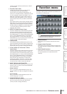
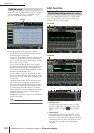
Here you can select the function that you want to view in
the display. These operate in the same way as the keys of
the DISPLAY ACCESS section.
Hint
To access this screen from another function, click the Func-
tion Name area at the top of the display.
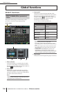
A Global functions
These buttons access functions that affect the entire
PM5D.
B Output-related functions
These buttons access functions related to output chan-
nels (MIX channels, MATRIX channels, STEREO A/B
channels).
C Input-related functions
These buttons access functions related to input chan-
nels (input channels, ST IN channels, FX RTN
channels).
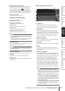
Function menu
1
2
3
Information shown
in the display
Function
menu
Global
functions
Output
functions
Input
functions
Appendices