


PM5D/PM5D-RH V2 / DSP5D Owner’s Manual Reference section 199
Information shown
in the display
Function
menu
Global
functions
Output
functions
Input
functions
Appendices
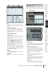
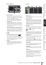
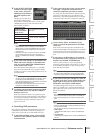
D LOCATE POINT
These buttons correspond to each locate point. Twenty
locate points can be specified for MMC-compatible
devices, and another twenty locate points can be sepa-
rately specified for RS422-compatible devices. When
you click buttons 1–20, an MMC command or RS422
command for moving to that locate point will be
transmitted.
E Time code
This field indicates the time code that is specified for
each locate point. To edit the time code, click the
button located at the left to open the MMC/RS422
LOCATE POINT window, and specify the new time
code in hours/minutes/seconds/frames. (In the case of
DENON format, use track/minute/second/frame units
to specify the value.) You can also use the CAPTURE
button located at the right to capture the time code
being received by the PM5D.
F CAPTURE
This button captures the time code currently being
received by the PM5D, and inputs it in the time code
field. In the case of MMC, the time code source, frame
rate, and offset time can be specified in the EVENT
LIST screen (SCENE function). (➥ p.177) In the case
of RS422, the time data at that moment for the exter-
nal device being controlled will be captured.
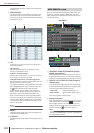
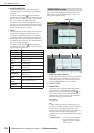
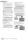
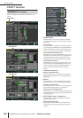
Here you can remotely control various functions of a
Yamaha DME series digital mixing engine.
Hint
As of this writing (April 2007), this function can be used with
the DME series models DME64N, DME24N, DME8i-C,
DME8o-C, DME4io-C, DME8i-ES, DME8o-ES and DME4io-
ES. (This function cannot be used with the DME32.)
A Component type selection area
Here you can select the type of DME series component
that you want to control from the PM5D. When you
click the / buttons at the left and right to select the
type of component, the display in the central area of
the screen will change accordingly. The following types
of component can be selected.
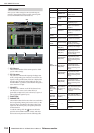
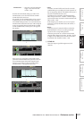
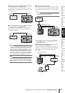
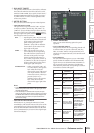
• SETUP
Select the port connecting the PM5D and the DME
series unit, and initiate or terminate communication.
• GEQ
Control the DME series unit’s graphic EQ from the
PM5D.
• PEQ
Control the DME series unit’s parametric EQ from the
PM5D.
• CROSS OVER
An internal signal within the DME series unit is divided
into six bands, and the output level, filter slope and
type, and cutoff frequency etc. can be controlled for
each band. This screen also lets you specify the cross-
over frequency at which the bands are divided.
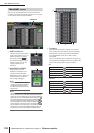
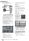
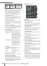
• LONG DELAY
• SHORT DELAY
Control the long delay and short delay functions of the
DME series unit from the PM5D.
• MATRIX
Specify the level of the signals sent from a specific input
of the DME series unit to all outputs, or from all inputs
to a specific output.
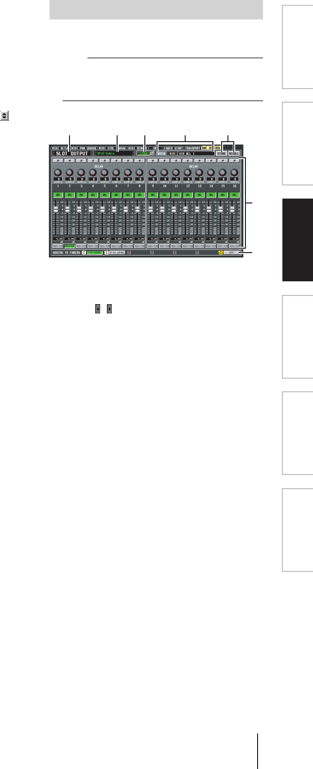
• SLOT OUTPUT
For each slot of the DME series unit, specify the out-
put level, delay time, and phase setting of each port.
B Component selection area
From the type of component you selected in 1, select
the component that you want to control.
DME CONTROL screen
6
7
541 2 3