


PM5D/PM5D-RH V2 / DSP5D Owner’s Manual Reference section 243
Information shown
in the display
Function
menu
Global
functions
Output
functions
Input
functions
Appendices
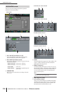
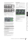
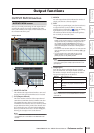
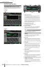
OUTPUT PATCH function
Here you can make patch settings to send output channel
signals to the outputs of I/O cards installed in the MIX
OUT jacks and slots, to the input of internal effects, and to
the 2TR OUT DIGITAL jacks.
A SELECTED PATCH
This indicates the output channel number, name and
output port of the grid at which the cursor is located.
B CH (Output channel)
This is the number and name of the output channel
(MIX channel, MATRIX channel, STEREO A/B chan-
nel, MONITOR L/R/C channel, CUE L/R channel,
TALKBACK OUT channel, OSC OUT channel) whose
output destination will be patched. The channel num-
ber at which the cursor is located will be highlighted.
When you click the name area, a window will appear,
allowing you to assign a name to the channel.
Note
On the PM5D, this is unavailable for the CUE L/R channels;
on the DSP5D, this is unavailable for the MONITOR L/R/C
channels.
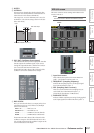
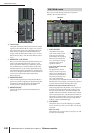
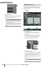
C ASSIGN
For each output channel, this indicates the number of
output ports that are currently assigned.
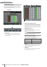
D Grid
This grid lets you patch output ports (horizontal rows)
to output channels (vertical columns). Currently-
patched grids are indicated by a symbol. By clicking
a grid location you can set/cancel patching.
The red lines at the left and top indicate the grid loca-
tion to which you move the cursor.
Hint
• If PATCH CONFIRMATION is turned on in the PREFER-
ENCE 1 screen (UTILITY function), a confirmation message
will appear each time you attempt to change a patch set-
ting. If STEAL PATCH CONFIRMATION is turned on, a
confirmation message will also appear when you attempt to
make patch settings that would cause an existing patch to
be modified.
• To move the cursor location rapidly in or out of the grid, hold
down the [SHIFT] key and press the CURSOR [
√
]/[
®
]/[
π
]/
[
†
] keys.
• To move rapidly to left or right inside the grid, turn the
[DATA] encoder. To move up or down, hold down the
[SHIFT] key and turn the [DATA] encoder.
Note
You can patch an output channel to more than one output
port, but you cannot patch multiple output channels to a sin-
gle output port.
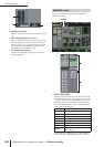
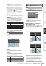
E Output port
From the top, this area indicates the type of output
port, the ID number, the output channel number, and
the number of output channels assigned. The follow-
ing types of output port can be selected.
Note
On the DSP5D, you can choose from OMNI OUT 1-24, SLOT
OUT 1-4 (SLOT OUT 3-4 is the CASCADE OUT connector),
and FX IN 1-8.
Output functions
OUTPUT PATCH screen
OUTPUT PATCH
5
1
2
34
MIX OUT MIX OUT jacks 1–24
SLOT OUT
Output channels of an I/O card installed in slots
1–4
FX IN
L/R inputs of internal effects 1–8 (MIX chan-
nels are the only output channels that can be
selected)
2TR OUT L/R channels of 2TR OUT DIGITAL jacks 1–3