


18 Surround pan
146 PM5D/PM5D-RH V2 / DSP5D Owner’s Manual Operating section
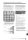
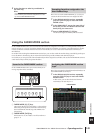
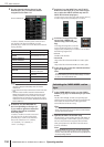
• Using the MIX encoders
If you turn on the [MIX SEND] key of the MIX sec-
tion, you can use MIX encoders 1 or 9 to adjust the
left/right position of the input channel, and MIX
encoders 2 or 10 to adjust the front/rear position. The
SURR PARAM screen MIX SECTION ASSIGNMENT
area shows the parameters assigned to each MIX
encoder.
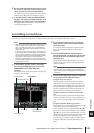
• Using MIDI control changes or GPI
If you assign surround pan parameters to MIDI con-
trol changes or GPI, you can use an external device to
control surround pan. For details, refer to MIDI CTRL
CHANGE screen (➥ p.191) and GPI screen (➥ p.194)
in the Reference section.
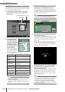
5
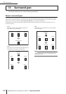
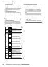
If you want surround pan operations to be
linked for two adjacent channels, turn on the
STEREO LINK button, and use the box at right
to select the link pattern.
When you turn on the STEREO LINK button, sur-
round pan will be linked for the two channels shown in
the SURR PARAM screen. To specify how they will be
linked, select one of the following link patterns by
clicking the / buttons at the left and right of the box
located to the right of the STEREO LINK button.
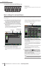
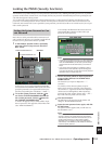
6
Edit other parameters as desired.
In the SURR PARAM screen you can also edit the fol-
lowing parameters.
• Divergence
These controls specify the proportion at which the sig-
nals are sent to each surround bus when the input
channel is positioned in the center. The parameters
that are displayed will depend on the surround mode
that is currently selected. (For details, refer to p.309)
•LFE
This adjusts the output level of the signal sent from the
input channel to the LFE (Low Frequency Effect) bus
for a subwoofer. You can also use the ON/OFF button
to switch the signal sent from the input channel to the
LFE bus on/off.
Hint
• The master level of each surround bus is shown in the upper
right of the screen.
• You can use the SURR VIEW screen to see the surround
pan settings of all channels at a glance.
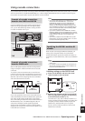
Pattern 1
The channels will move in the same
direction for both the front/rear axis
and the left/right axis.
Pattern 2
The channels will move in opposite
directions for the front/rear axis, and in
the same direction for the left/right
axis.
Pattern 3
The channels will move in the same
direction for the front/rear axis, and in
opposite directions for the left/right
axis.
Pattern 4
Left↔right movement of the odd-num-
bered channel will be linked with
rear↔front movement of the even-
numbered channel. Front↔rear move-
ment of the odd-numbered channel
will be linked with left↔right move-
ment of the even-numbered channel.
Pattern 5
Left↔right movement of the odd-num-
bered channel will be linked with
front↔rear movement of the even-
numbered channel. Front↔rear move-
ment of the odd-numbered channel
will be linked with left↔right move-
ment of the even-numbered channel.
Pattern 6
Front/rear and left/right movement will
both be linked in the opposite direc-
tion.
Pattern 7
Left↔right movement of the odd-num-
bered channel will be linked with
front↔rear movement of the even-
numbered channel. Front↔rear move-
ment of the odd-numbered channel
will be linked with right↔left move-
ment of the even-numbered channel.
Pattern 8
Left↔right movement of the odd-num-
bered channel will be linked with
rear↔front movement of the even-
numbered channel. Front↔rear move-
ment of the odd-numbered channel
will be linked with left↔right move-
ment of the even-numbered channel.