


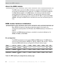
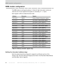
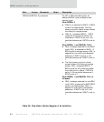

MEM module configuration
94
NS7520 Hardware Reference, Rev. D 03/2006
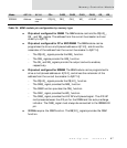
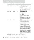
D11:10 R/W PGSIZE 0 Peripheral page size
Defines the page size for the attached
peripheral with this equation:
2
(6–PGSIZE)
The NS7520 halts a burst at the address
boundary defined by the PGSIZE field.
This field must be set to ‘b00 for 32-bit
operation of the chip select.
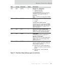
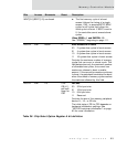
D09:08 R/W DMODE 0 DRAM configuration mode
00 FP DRAM
01 EDO DRAM
10 SDRAM
11 Reserved
Controls the DRAM type when the
memory device is configured to operate in
DRAM mode. This field is used only when
the DRSEL bit is set to 1 (DRAM mode).
All DRAM memory peripherals must be
configured as the same type of DRAM.
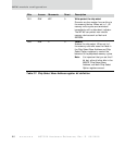
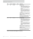
D07 R/W DMUXS 0 DRAM address multiplexer select
0 Use internal DRAM multiplexer
1 Use external DRAM multiplexer
Controls whether the NS7520 uses the
internal address multiplexer for this DRAM
memory peripheral.
1 indicates that an external DRAM
multiplexer is to be used for this chip
select, where PORTA2 determines when
the external multiplexer switches the
address bits. When the PORTA2 signal is
active high, the external DRAM RAS/CAS
address multiplexer function must drive
the CAS address to the DRAM devices.
The AMUX or AMUX bits in the MMCR
serve as a global control when set. When
either of these bits is set to 1, all DRAM
peripheral devices use the external
address multiplexer and the DMUXS bit is
ignored.
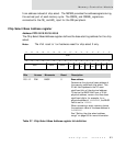
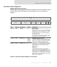
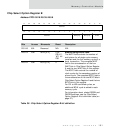
Bits Access Mnemonic Reset Description
Table 37: Chip Select Base Address register bit definition