


NS7520 DRAM address multiplexing
108
NS7520 Hardware Reference, Rev. D 03/2006
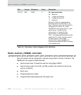
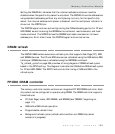
Using the external multiplexer
An external address multiplexer is required when the selected SDRAM component
cannot interface with the NS7520 internal multiplexer. Although an external address
multiplexer is used, the NS7520 memory controller can control the basic DRAM signal
protocol. The NS7520 can be configured to output the DRAM address multiplexer
signal out the PORTA2 pin, by setting the AMUX or AMUX2 bit in the MMCR or by
setting the DMUXS bit in the Chip Select Base Address register.
Setting the AMUX bit indicates that the internal address multiplexer must be
disabled. When AMUX is set, the NS7520 drives the address bus using standard
addressing without any multiplexing, the internal multiplexer is disabled, and the
multiplexer indicator is driven out the PORTA2 pin.
The AMUX2 bit allows the internal bus masters to use the internal address
multiplexer, and forces the PORTA2 signal to be driven.
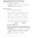
NS7520
pin
A23 A22 A13 A12 A11 A10 A9 A8 A7 A6 A5 A4 A3 A2 A1 A0
DRAM
pin
A13 A12 A11 A10 A9 A8 A7 A6 A5 A4 A3 A2 A1 A0
RAS 22 21 20 19 18 17161514131211109
CAS 2200010987654321
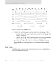
16-bit DRAM peripheral (22 address bits: 14 RAS and 8 CAS)
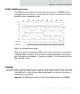
NS7520
pin
A23 A22 A13 A12 A11 A10 A9 A8 A7 A6 A5 A4 A3 A2 A1 A0
DRAM
pin
A13 A12 A11 A10 A9 A8 A7 A6 A5 A4 A3 A2 A1 A0
RAS 23 22 21 20 19 18 1716151413121110
CAS23220001098765432
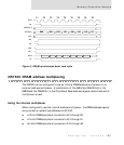
32-bit DRAM peripheral (22 address bits: 14 RAS and 8 CAS)
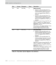
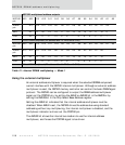
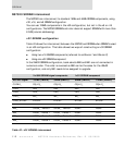
NS7520 multiplexed address outputs
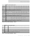
Table 41: Internal DRAM multiplexing — Mode 1