


www.digi.com
105
Memory Controller Module
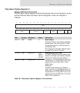
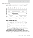
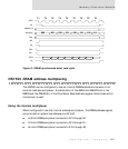
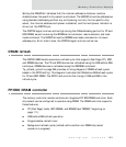
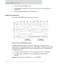
Figure 8: SRAM synchronous burst read cycle
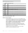
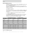
NS7520 DRAM address multiplexing
The NS7520 can be configured to use an internal DRAM address multiplexer or an
external address multiplexer. A combination of the AMUX and AMUX2 bits in the
MMCR and the DMUXS bit in the Chip Select Base Address register determines which
multiplexer is used.
Using the internal multiplexer
When configured to use the internal address multiplexer, the DRAM address signals
are provided on system bus address pins A13:A0.
A 32-bit DRAM peripheral connects to A13 through A2.
A 16-bit DRAM peripheral connects to A13 through A1.
An 8-bit DRAM peripheral connects to A13 through A0.
T1 T2 T2 T2 T2 T2 T2 T2 T2
000 001 010 011 100 101 110 111
BCLK
CS_
ADDR[31:4]
ADDR[3:1]
R/W_
WE_
OE_
BE0_
BE1_
DATA
TA_