


SDRAM
118
NS7520 Hardware Reference, Rev. D 03/2006
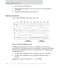
Memory timing fields — SDRAM
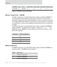
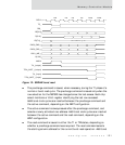
The WAIT configuration in the Chip Select Option register provides the SDRAM T
RCD
and T
RP
parameters. When WAIT is configured with a value of 0, the active and
precharge commands can be followed immediately by another command on the next
active edge of BCLK. When WAIT is configured with a value larger than 0, wait states
are inserted after the active and precharge commands before another command can
be issued.
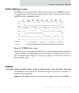
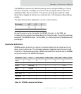
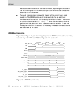
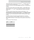
The BCYC configuration in the Chip Select Option register provides the SDRAM CAS
latency parameter. The BCYC field must be set to a value of
CAS latency - 1. The
NS7520 can support SDRAMs that have a CAS latency specification between 1 and 4
BCLK clocks, as shown:
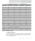
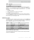
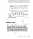
BSIZE configuration
The BSIZE configuration in the Chip Select Option register provides the SDRAM burst
length parameter. The BSIZE field is set as shown:
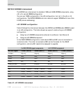
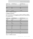
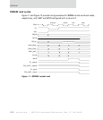
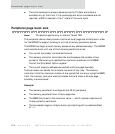
Load mode 0 Op-code 0 0 0 0
Command
CSx_ A13:0 CAS3_ RAS# CAS2_ CAS# CAS1_ WE# CAS0_ A10/AP
Table 45: SDRAM command definitions
CAS latency BCYC configuration
100
201
310
411
BSIZE Burst length
00 2 words (not supported)
01 4 words (not supported)
10 8 words (not supported)