


GEN module registers
74
NS7520 Hardware Reference, Rev. D 03/2006
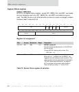
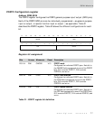
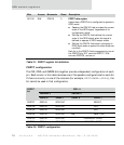
PORTA Configuration register
Address: FFB0 0020
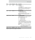
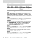
The PORTA register configures the PORTA general-purpose input/output (GPIO) pins.
Each of the PORTA GPIO pins can be individually programmed — as general-purpose
input or output, or special function input or output — as applicable. Table 29
describes the PORTA register; Table 30 shows the different configurations for each
bit.
Register bit assignment
Bits Access Mnemonic Reset Description
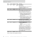
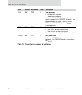
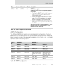
D31:24 R/W AMODE 0 PORTA mode configuration
0 Selects GPIO mode
1 Selects special function mode
Configures the individual PORTA pins. Each bit in
the AMODE field corresponds to one of the PORTA
bits; D31 controls PORTA7, D30 controls
PORTA6, and so on.
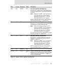
D23:16 R/W ADIR 0 PORTA data direction
0 Selects input mode
1 Selects output mode
Configures the individual PORTA pins. Each bit in
the ADIR field corresponds to one of the PORTA
bits; D23 controls PORTA7, D22 controls
PORTA6, and so on.
D15:08 N/A Reserved N/A N/A
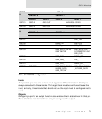
Table 29: PORTA register bit definition
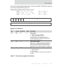
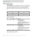
13121110987654321015 14
31 29 28 27 26 25 24 23 22 21 20 19 18 17 1630
AMODE ADIR
Reserved ADATA