


www.digi.com
145
DMA Module
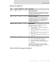
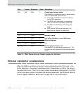
Ethernet receiver considerations
When an Ethernet frame is received, DMA channel 1 searches the four buffer
descriptors for the optimum buffer size. The search order is A, B, C, D. The search
stops as soon as the DMA channel finds an available buffer that is large enough to hold
the entire frame. The search also stops when the DMA channel finds a DMA Control
register whose CE bit is set to zero.
Because interrupts are set when DMA channel 1 encounters buffers that are not
ready, the device driver should be designed with the smallest buffers in the A pool
and the largest buffers in the D pool. The number of available pools can be
configured, from 1
to 4, with proper use of the CE bits.
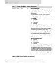
An Ethernet receive FIFO overrun condition can occur (the FIFO becomes full while
receiving an Ethernet packet) if insufficient buffers are allocated by the application.
If this condition occurs (signaled by the NRIP bit in the DMA Channel 1 Status
register), you must use this procedure to guarantee successful operation:
1 Set the ERXDMA, in the Ethernet General Control register, to zero.
2 SET the ERX bit, in the Ethernet General Control register, to zero.
3 Set the CE bit, in the DMA Control register, to zero.
4 Add new buffers for Ethernet DMA.
5 Restore the DMA Control register.
6 Restore the ERX bit.
7 Restore the ERXDMA bit.
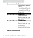
External peripheral DMA support
DMA channels 3, 4, 5, and 6 can be set up for external DMA transfers, using three
signals — DREQ_, DACK_, and DONE_ — to facilitate communications between the
NS7520 and an external device. It is up to the external device to source or react to
these signals. The external device can be a block of memory using memory-to-
memory transfers. Within every transaction on the bus, a cycle on the external bus is
executed corresponding to timing generated by the MEM module.