


www.digi.com
235
Serial Controller Module
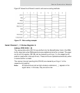
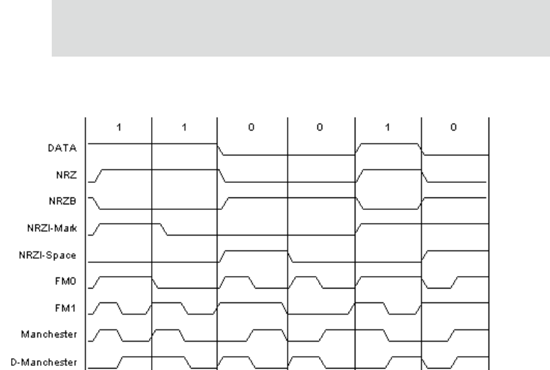
Figure 27 shows the different transmit and receive coding methods.
Figure 27: Data coding example
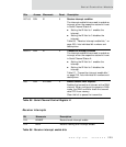
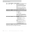
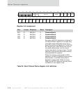
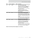
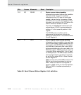
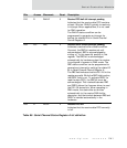
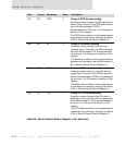
Serial Channel 1, 2 Status Register A
Address: FFD0 0008 / 48
The receive status bits (D31:16) are stuffed into the StatusOrIndex field in the DMA
buffer descriptor when DMA operations are enabled and a buffer is closed. The upper
six bits of this register (D31:26) can be cleared by writing a 1 to the respective bit
position (used when interrupt-driven). These six bits are updated automatically when
a receive buffer is closed.
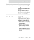
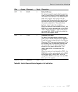
The receive interrupt pending bits (D15:00) are cleared by writing a 1 to the
respective bit position.
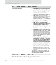
Note:
All status bits are active high unless an underscore ( _ ) appears in the
signal name; in this case, they are active low.