


SPI mode
218
NS7520 Hardware Reference, Rev. D 03/2006
3 Configure the buffer GAP timer, if you want. The buffer GAP timer terminates a
DMA transfer at a programmable interval from the time the first character is
received. (See "Serial Channel 1, 2 Receive Buffer Gap Timer," beginning on page
255, for more information).
4 Configure the character GAP timer, if you want. The character GAP timer
terminates a DMA transfer if the time between the receipt of two characters
exceeds a programmable interval. (See "Serial Channel 1, 2 Receive Character
Gap Timer," beginning on page 256, for more information.)
5 Configure Serial Channel Control Register B as shown:
– RBGT: 1 to enable the buffer GAP timer
– RCGT: 1 to enable the character GAP timer
– MODE: 10 for master mode
– BITORDR: user-defined
6 Configure Serial Channel Control Register A as shown:
– CE: 1 for enable
– WLS: 11 for 8-bit operation
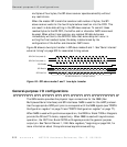
SPI master transmitter
The SPI master transmitter operates as follows:
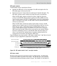
Changes its TXD output on the falling edge of the SPI clock signal while the
SPI enable signal is driven active low. The SPI slave devices should sample
data in the rising edge of the SPI clock signal.
Drives the SPI enable signal active low from the falling edge of the SPI clock
for the first bit of a byte being transmitted, and inactive high after the
rising edge of the SPI clock signal during the eighth bit of the byte currently
transmitted.
Drives the SPI enable signal active low to identify when data is being
transmitted. The SPI clock signal never transitions from low to high while
the internal SPI enable signal is inactive high.
Transmits bytes when data is available in the TX FIFO. When the TX FIFO
becomes empty, the SPI enable signal is driven inactive high until more data
is available in the TX FIFO.