


www.digi.com
133
DMA Module
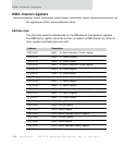
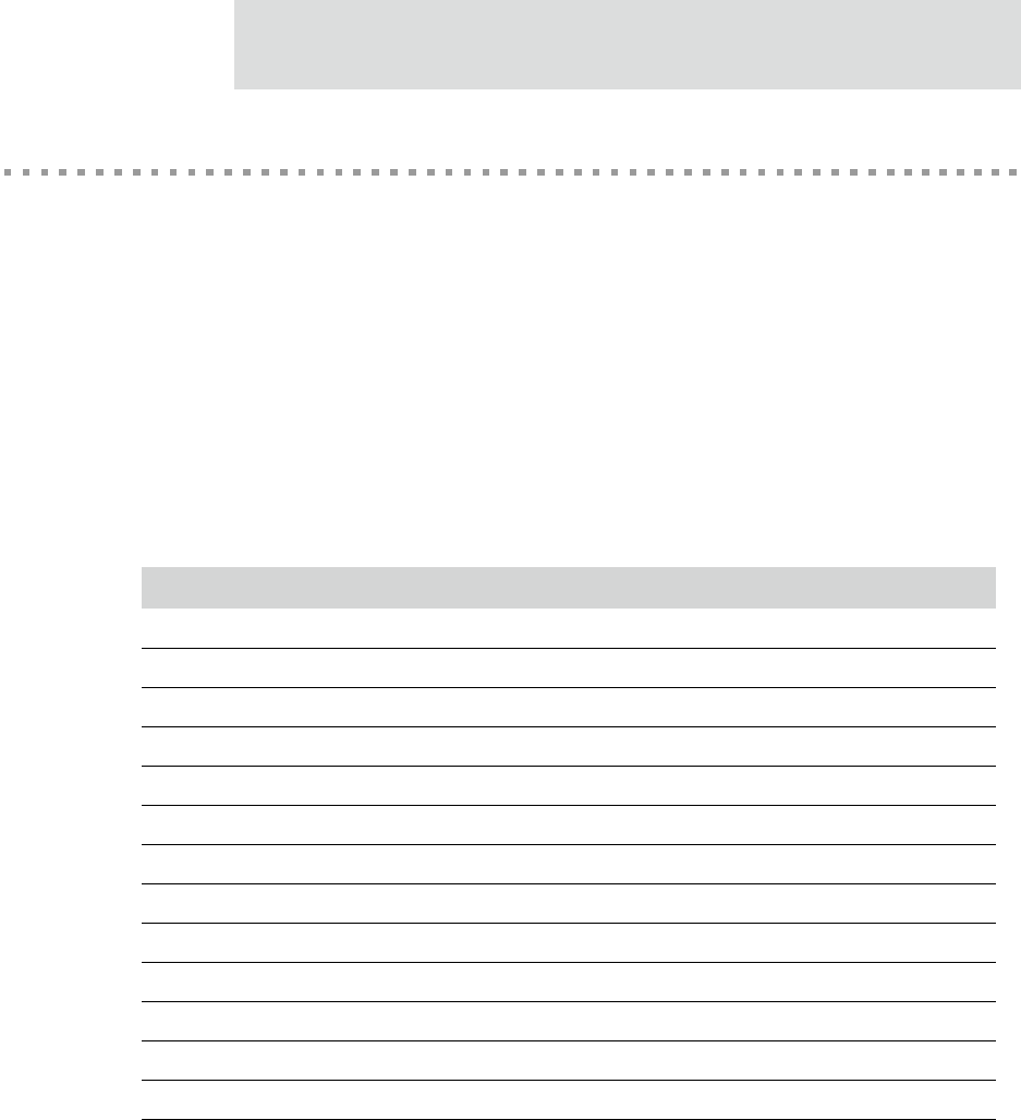
DMA channel assignments
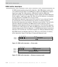
Any of the 13 channels in the DMA controller can be configured for memory-to-
memory mode. Those channels assigned to a peripheral (see Table 49, “DMA channel
assignments,” on page 133) can be configured for fly-by mode.
FB write indicates fly-by peripheral-to-memory.
FB read indicates fly-by memory-to-peripheral.
MM indicates memory-to-memory.
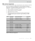
DMA channels 3/5 and 4/6 can interface with external peripheral devices
using DMA handshake signals multiplexed through the GPIO pins in PORTA
and PORTC.
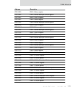
Channel Base address DMA channel peripheral Fly-by mode
1 ’hFF90 0000 Ethernet port 1 receiver FB write
2 ’hFF90 0080 Ethernet port 1 transmitter FB read
3 ’hFF90 00A0
4 ’hFF90 00C0
5 ’hFF90 00E0
6 ’hFF90 0100
7 ’hFF90 0120 SER channel 1 receiver FB write
8 ’hFF90 0140 SER channel 1 transmitter FB read
9 ’hFF90 0160 SER channel 2 receiver FB write
10 ’hFF90 0180 SER channel 2 transmitter FB read
11 ’hFF90 01A0 MM
12 ’hFF90 01C0 MM
13 ’hFF90 01E0 MM
Table 49: DMA channel assignments