


Static memory (SRAM) controller
102
NS7520 Hardware Reference, Rev. D 03/2006
Static memory (SRAM) controller
Each chip select can be configured to operate using a static memory interface. The
SRAM controller supports these features:
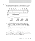
Synchronous mode: Transactions use the rising edge of BCLK
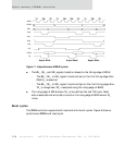
Asynchronous mode: Force OE_ and WE_ pulses to be inside the active low
portion of CS[4:0]_
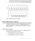
Burst cycle
Programmable wait states
Programmable base address and chip select size
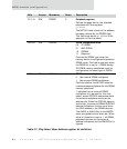
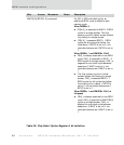
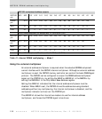
D01:00 R/W SYNC 0 TA_ input synchronizer
00 Reserved
01 1-stage synchronizer
10 2-stage synchronizer
11 Reserved
Defines the level of synchronization
performed within the NS7520 for TA_
input. Used only when the chip select is
configured for external TA_ mode.
The NS7520 can process the TA_ input
signal using a 1-stage flip-flop
synchronizer, a 2-stage flip-flop
synchronizer, or no synchronizer.
The 1- or 2-stage synchronizers must be
used if the TA_ input is synchronous to
the BCLK signal. (The 2-stage
synchronizer is recommended as it
introduces one additional BCLK of latency
in the access cycle.
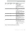
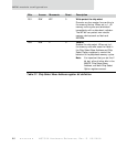
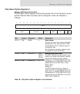
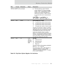
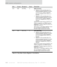
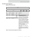
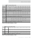
Bits Access Mnemonic Reset Description
Table 39: Chip Select Option Register B bit definition