


www.digi.com
55
SYS Module
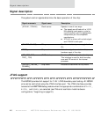
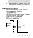
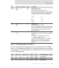
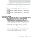
The next table shows the 32 frequencies that can be produced with an 18.432MHz
crystal. A 0 on an address indicates that a 2.7K pulldown resistor must be connected
to that address line. The table shows the IS, FS, and ND fields, and the resulting value
in the PLL Settings register.
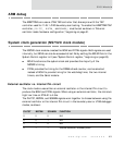
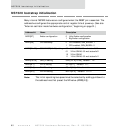
D08:07 Read
only
IS ‘b10 Charge pump current
Sets the PLL’s charge pump current.
The IS field defaults to binary ‘b10 when address
lines [8:7] are not pulled down on powerup. The
IS value is based on the value in the ND field.
(ND+1) IS
1–3 ‘b00
4–7 ‘b01
8–15 ‘b10
16–32 ‘b11
D06:05 Read
only
FS ‘b00 Output divider
Sets the PLL’s output divider.
The FS field defaults to ‘b00 when address lines
[6:5] are not pulled down on powerup. This is the
correct setting for all frequencies and should
never be adjusted.
D04:00 Read
only
ND ‘b01011 PLL multiplier
Sets the PLL’s multiplier, which determines BCLK
frequency.
BCLK frequency is based on tis formula:
BCLK = (crystal/4) (ND+1)
The ND field defaults to ‘b01011 to produce
55MHz (with a 18.432MHz crystal) when
address lines A[4:0] are not pulled down on
powerup.
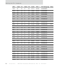
MHz A[8:7] IS A[6:5] FS A[4:0] ND+1 PLL Settings reg Notes
4.6 01 00 11 00 10100 00001 0x00000000
9.2 01 00 11 00 10101 00010 0x00000001
13.8 01 00 11 00 10110 00011 0x00000002
Bits Access Mnemonic Reset Description
Table 21: PLL Settings register bit definition