


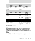


Interrupts
82
NS7520 Hardware Reference, Rev. D 03/2006
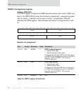
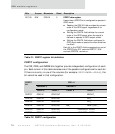
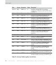
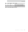
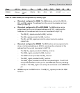
Bits Access Mnemonic Reset Description
D31:19 R/W DMA1–13 0 The DMA1 through DMA13 bit positions
correspond to interrupts sourced by DMA channel
1 through 13.
D18 N/A Reserved N/A N/A
D17 R/W ENET1RX 0 The ENET1RX bit position corresponds to an
interrupt sourced by the Ethernet receiver.
D16 R/W ENET1TX 0 The ENET1TX bit position corresponds to an
interrupt sourced by the Ethernet transmitter.
D15 R/W SER 1 RX 0 The SER 1 RX bit position corresponds to an
interrupt sourced by the Serial Channel A receiver.
D14 R/W SER 1 TX 0 The SER 1 TX bit position corresponds to an
interrupt sourced by the Serial Channel A
transmitter.
D13 R/W SER 2 RX 0 The SER 2 RX bit position corresponds to an
interrupt sourced by the Serial Channel B receiver.
D12 R/W SER 2 TX 0 The SER 2 TX bit position corresponds to an
interrupt sourced by the Serial Channel B
transmitter.
D11:08 N/A Reserved N/A N/A
D07 R/W MAC1 0 The MAC1 bit position corresponds to an interrupt
sourced by the Ethernet MAC 1.
D06 R/W
WATCHDOG
0 The WATCHDOG bit position corresponds to an
interrupt condition sourced by the watchdog timer.
D05 R/W TIMER 1 0 The TIMER 1 bit position corresponds to an
interrupt condition sourced by the TIMER 1
module.
D04 R/W TIMER 2 0 The TIMER 2 bit position corresponds to an
interrupt condition sourced by the TIMER 2
module.
D03 R/W PORTC3 0 The PORTC3 bit position corresponds to an
interrupt condition sourced by the PORTC3 input.
D02 R/W PORTC2 0 The PORTC2 bit position corresponds to an
interrupt condition sourced by the PORTC2 input.
Table 33: Interrupt Enable registers bit definition