


GEN module registers
76
NS7520 Hardware Reference, Rev. D 03/2006
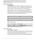
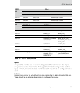
Inputs
An input that provides one or more input signals to different blocks in the chip is
always connected to those blocks. The target block must be configured to use the
input; similarly, those blocks that should not use the input must be configured not to
use it.
Outputs
Configuring a pin for an output function also enables the tri-state driver for that pin.
There should be no external driver on a pin configured for output.
READBACK
When reading the ADATA field, the data read depends on how the pin is configured:
Configured as GPIO output. Reads data from the register whose data drives
the pin. This can, for example, mask a short circuit on the output pin.
All other configurations. Reads the state of the pin.
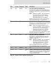
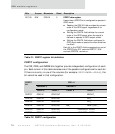
PORTA4
When PORTA4 is configured with
AMODE[4]=1:ADIR[4]=1, the configuration of Serial
Channel A determines the function
SER1_SPI_M_CLK_OUT, SER1_OUT1, SER1_RXC_OUT.
PORTA2
The memory module configures the AMUX output signal. The AMUX configuration
overrides the AMODE, ADIR, and ADATA fields.
PORTA0
When PORTA0 is configured with
AMODE[0]=1:ADIR[0]=1, the configuration of Serial
Channel A determines the function
SER1_SPI_M_ENABLE_A_ OUT or SER1_OUT2.
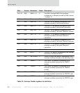
PORTA1 GPIO IN GPIO OUT SER1_CTS DONE1_OUT_
PORTA0 GPIO IN GPIO OUT SER1_SPI_S_ENABLE_
IN/SER1_DCD_/
DONE1_IN_/
SER1_TXC IN
SER1_SPI_M_ENABLE_
OUT/SER1_OUT2
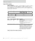
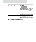
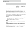
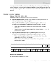
PORTA
bit
AMODE=0 AMODE=1
ADIR=0 ADIR=1 ADIR=0 ADIR=1
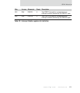
Table 30: PORTA configuration